Eureka AIR delivers breakthrough ideas for toughest innovation challenges, trusted by R&D personnel around the world.

Generating clip state for a batch of vertices

a technology of clip state and batch vertices, applied in the field of graphic processing, can solve the problems of unnecessarily waste of memory bandwidth and processing resources of the gpu to process graphics primitives, and achieve the effects of reducing cull and clip units, preserving processing bandwidth, and reducing computational load on the viewport scal

Active Publication Date: 2015-03-10
NVIDIA CORP
View PDF55 Cites 51 Cited by
  • Summary
  • Abstract
  • Description
  • Claims
  • Application Information

AI Technical Summary

Benefits of technology

The disclosed technique involves generating a clip state machine early in the graphics pipeline, which helps conserve processing bandwidth and reduce computational load on the viewport scale, cull and clip unit. This means that only vertices in a specific clip state need to be processed by the viewport scale, cull and clip unit, resulting in improved efficiency and performance.

Problems solved by technology

One drawback of a conventional graphics processing pipeline, is that operations in stages prior to the clipping and culling stage are performed for each of the graphics primitives regardless of whether those graphics primitives are clipped or culled downstream.
In such a scenario, memory bandwidth and processing resources of the GPU are wasted unnecessarily to process graphics primitives and vertices of those graphics primitives that are discarded at a later stage.

Method used


Image

  • Generating clip state for a batch of vertices
  • Generating clip state for a batch of vertices
  • Generating clip state for a batch of vertices

Examples


Embodiment Construction

[0025]In the following description, numerous specific details are set forth to provide a more thorough understanding of the present invention. However, it will be apparent to one of skill in the art that the present invention may be practiced without one or more of these specific details. In other instances, well-known features have not been described in order to avoid obscuring the present invention.

System Overview

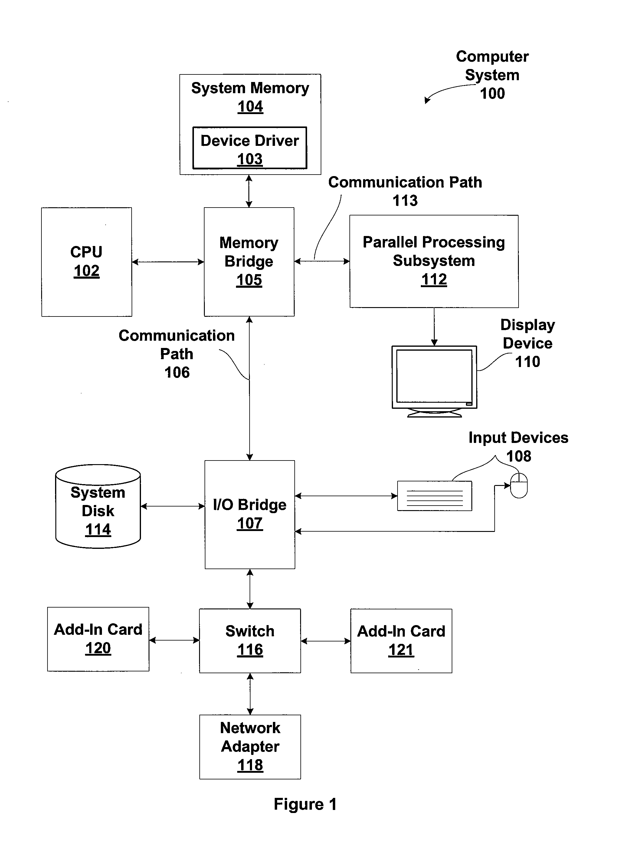
[0026]FIG. 1 is a block diagram illustrating a computer system 100 configured to implement one or more aspects of the present invention. Computer system 100 includes a central processing unit (CPU) 102 and a system memory 104 communicating via an interconnection path that may include a memory bridge 105. Memory bridge 105, which may be, e.g., a Northbridge chip, is connected via a bus or other communication path 106 (e.g., a HyperTransport link) to an I / O (input / output) bridge 107. I / O bridge 107, which may be, e.g., a Southbridge chip, receives user input from one or mor...


PUM


Abstract

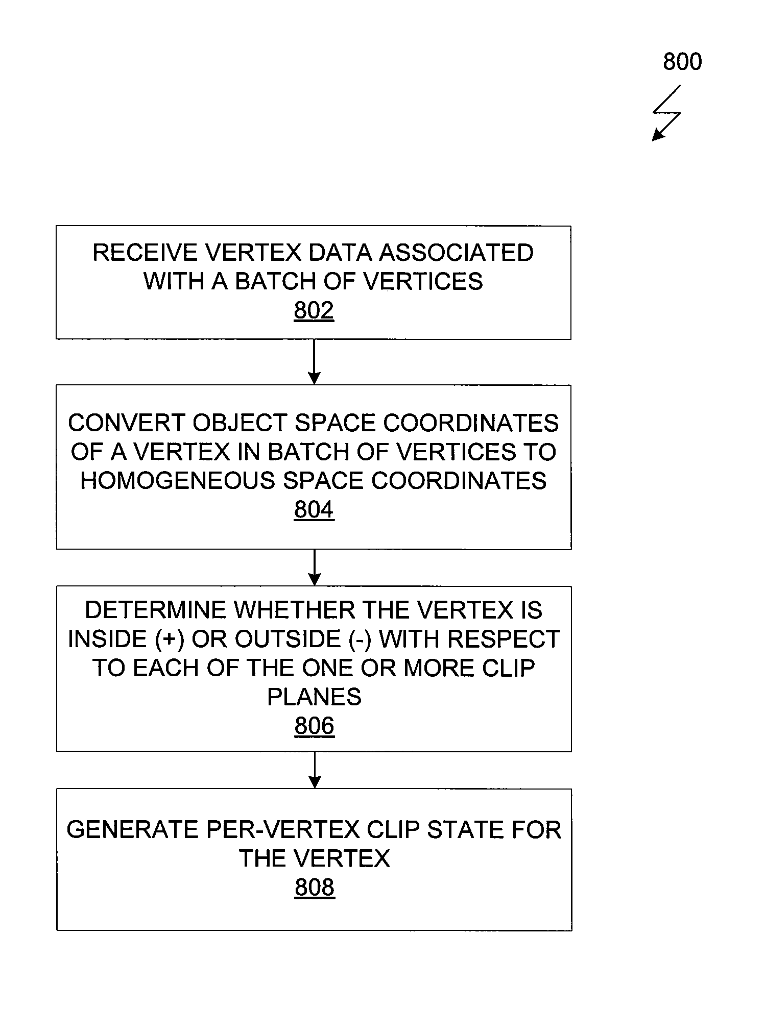
One embodiment of the present invention sets forth a technique for generating a batch clip state stored in clip state machine (CSM) associated with a batch of vertices. Per-vertex clip state is generated for each vertex in the batch of vertices based on the position of each vertex relative to each clip plane. For a given vertex, per-vertex clip state indicates whether the vertex is inside or outside each of the one or more clip planes. The per-vertex clip states of all the vertices in the batch of vertices are coalesced into a batch clip state by determining whether each vertex in the batch of vertices is inside every clip plane, each vertex is outside at least one clip plane or neither. The batch clip state is stored in the CSM associated with the thread group that processes the batch of vertices that can be accessed by further stages of the graphics pipeline.

Description

BACKGROUND OF THE INVENTION[0001]1. Field of the Invention[0002]The present invention generally relates to the field of graphics processing and more specifically to generating a clip state via a clip state machine for a batch of vertices.[0003]2. Description of the Related Art[0004]A graphics processing pipeline of a graphics processing unit (GPU) accepts a representation of a three-dimensional (3D) scene as an input and processes that input to produce a 2D display image of the scene as an output. As is well known, the 3D graphics scene is typically represented by a collection of primitives having vertices. Indices associated with the vertices are stored in index arrays, and vertex data associated with those vertices is stored in vertex arrays. The primitives are individually processed by the GPU based on the index arrays and the vertex data when generating the 2D display image of the scene.[0005]A conventional graphics processing pipeline has different stages through which the prim...

Claims


Application Information

Patent Timeline
Patent Type & Authority Patents(United States)
IPC IPC(8): G09G5/00G06T15/30
CPCG06T15/30
Inventor LINDHOLM, JOHN ERIKHAKURA, ZIYAD S.
Owner NVIDIA CORP
Why Eureka
Eureka Blog
Learn More