
Cathode mix having improved efficiency and energy density of electrode

a cathode mix and energy density technology, applied in the direction of cell components, secondary cell maintenance/maintenance, maintenance/maintenance of primary cells, etc., can solve the problems of low stability and high cost, unsuitable for mass-production at a reasonable cost, and reduce the efficiency of anodes. , the effect of reducing the efficiency of anodes

Active Publication Date: 2015-02-24
LG ENERGY SOLUTION LTD
View PDF19 Cites 1 Cited by
  • Summary
  • Abstract
  • Description
  • Claims
  • Application Information

AI Technical Summary

Benefits of technology

The present invention provides a solution for improving the efficiency and capacity of batteries. By controlling the molar fraction of phosphorus in high-efficiency lithium iron phosphate, the invention can level the efficiency of the cathode active material to a lower level of the anode active material, minimize electrode efficiency waste, and maximize efficiency and capacity. Additionally, controlling the Fe valence can improve the IR drop and rate properties, enhance the charge / discharge plateau potential, and maximize energy density.

Problems solved by technology

LiCoO2 is currently used owing to superior physical properties such as cycle life, but has disadvantages of low stability and high-cost due to use of cobalt, which suffers from natural resource limitations, and limitations of mass-use as a power source for electric automobiles.
LiNiO2 is unsuitable for practical application to mass-production at a reasonable cost due to many features associated with preparation methods thereof.
Lithium manganese oxides such as LiMnO2 and LiMn2O4 have a disadvantage of short cycle life.
However, such an olivine-type LiFePO4 has an operational efficiency of about 100%, thus making it difficult to control with the operational efficiency of an anode.
As a result, 10% of the efficiency of the cathode is disadvantageously wasted.
Accordingly, when a material having an efficiency of 100% is used as a cathode active material, the electrode material is disadvantageously wasted in direct proportion to the irreversible capacity of about 10 to 20%.
In addition, when an anode active material having relatively low efficiency is used, an amount of anode active material used should be increased, depending on a higher efficiency of a cathode, which disadvantageously entails an increase in manufacturing costs.
In this case, the selection range of an anode active material is disadvantageously narrowed.
However, to date, there is no technology suggesting a method for controlling efficiency of LiFePO4 as a cathode active material.

Method used


Image

  • Cathode mix having improved efficiency and energy density of electrode
  • Cathode mix having improved efficiency and energy density of electrode
  • Cathode mix having improved efficiency and energy density of electrode

Examples


examples

[0053]Now, the present invention will be described in more detail with reference to the following examples. These examples are provided only for illustrating the present invention and should not be construed as limiting the scope and spirit of the present invention.

preparation examples 1-4

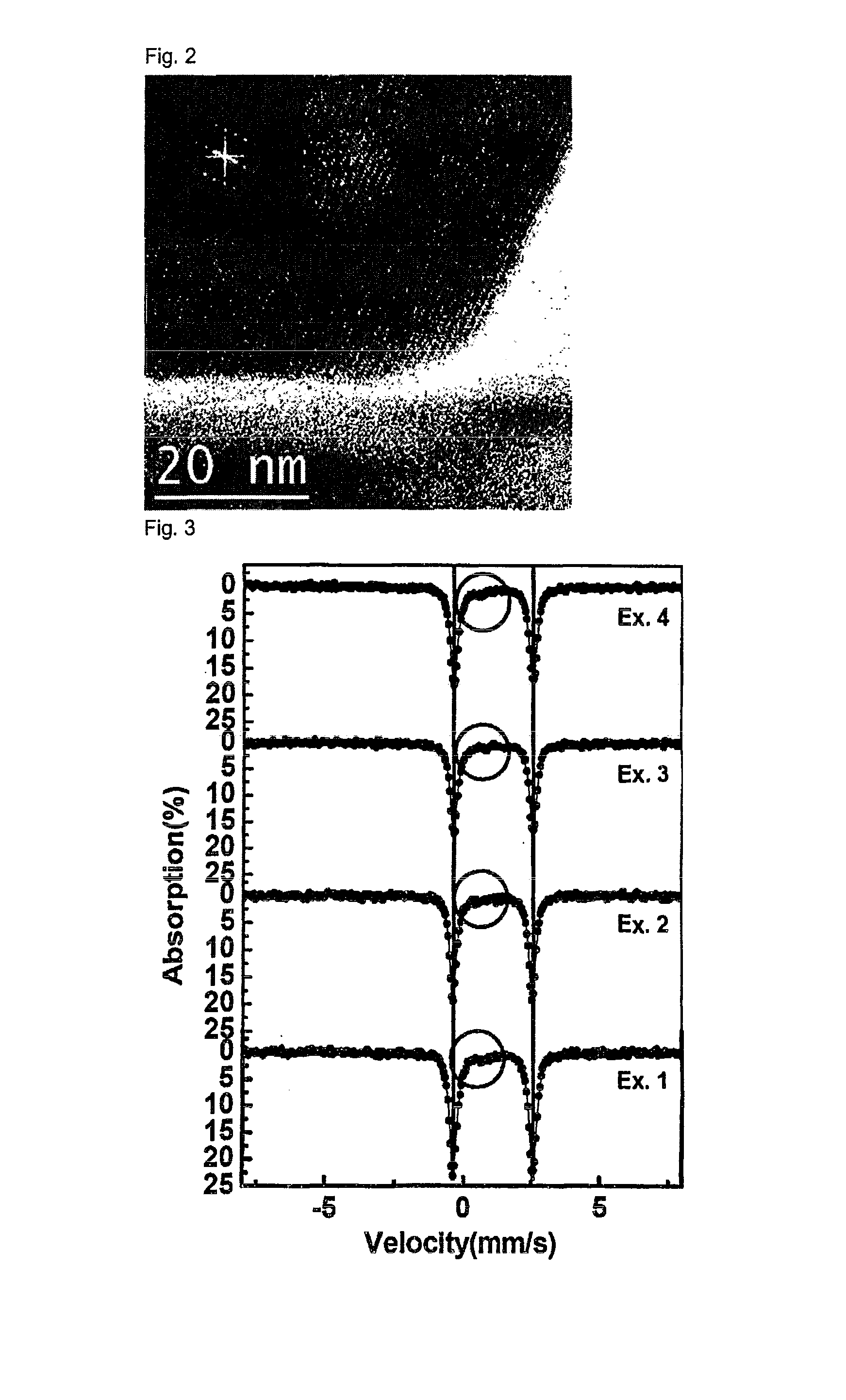
[0054]Cathode active materials (LiFeP1-xO4) wherein the content of phosphorus (P) is 0.94 (Preparation Example 1), 0.96 (Preparation Example 2), 0.97 (Preparation Example 3) and 0.985 (Preparation Example 4) were prepared by a hydrothermal process, well-known as a LiFePO4 preparation method, in accordance with the following process. A more detailed description will be given below.

[0055]A solution of lithium hydroxide (LiOH—H2O) and iron sulfate (FeSO4-6H2O) as Li and Fe sources in distilled water and phosphoric acid (H3PO4) as a P source were placed in a reaction chamber. The molar ranges of these materials placed in the reaction chamber were as follows: FeSO4: 0.5 mol, LiOH—H2O: 0.5 mol-1.5 mol, H3PO4: 0.5 mol-0.6 mol.

[0056]The reaction was carried out in the reaction chamber at 380° C. for 15 sec. The reaction pressure was maintained at 270 bar using a pressure controller. When an excess of Li and P compounds are added in hydrothermal reactions generally having a slow reaction rat...

example 1

[0057]90% by weight of LiFeP0.94O4 prepared in Preparation Example 1, as the cathode active material, 5% by weight of Super-P as a conductive material and 5% by weight of PVdF as a binder were added to NMP (N-methyl-2-pyrrolidone) to prepare a cathode mixture slurry. The cathode mixture slurry was coated on one surface of an aluminum foil, followed by drying and pressing, to fabricate a cathode.

[0058]95% by weight of carbon as an anode active material, 1.5% by weight of Super-P as a conductive material and 3.5% by weight of PVdF as a binder were added to NMP as a solvent, to prepare an anode mix slurry. The anode mix slurry was coated on one surface of an aluminum foil, followed by drying and pressing, to fabricate an anode.

[0059]An electrode assembly was fabricated by laminating the cathode and the anode using Cellguard™ as a separator and a lithium non-aqueous electrolyte containing 1M LiPF6 in cyclic and linear carbonate mix solvent was added to the electrode assembly to fabricat...


PUM

PropertyMeasurementUnit
thicknessaaaaaaaaaa
thicknessaaaaaaaaaa
pore diameteraaaaaaaaaa

Abstract

Provided is a cathode mix for lithium secondary batteries, comprising a cathode active material having a composition represented by the following Formula I: LiFe(P1-XO4) (I) wherein a molar fraction (1−x) of phosphorus (P) is in the range of 0.910 to 0.999, to allow operational efficiency of the cathode active material to be leveled to a lower operational efficiency of an anode active material and improve energy density of the cathode active material.The cathode mix maximizes operational efficiency of batteries, minimizes electrode waste and thus reduces manufacturing costs of batteries. Furthermore, The cathode active material, wherein a molar fraction (1−x) of phosphorus (P) is lower than 1, according to the present invention contains both Fe2+ and Fe3+, thus advantageously causing no structural deformation, improving ionic conductivity, exhibiting superior rate properties, inhibiting IR drop upon charge / discharge, thereby imparting high energy density to batteries.

Description

[0001]This application is a Continuation of copending PCT International Application No. PCT / KR2009 / 006082 filed on Oct. 21, 2009 which designated the United States, and on which priority is claimed under 35 U.S.C. §120. This application also claims priority under 35 U.S.C. §119(a) on Patent Application No. 10-2008-0103553 filed in the Republic of Korea on Oct. 22, 2008. The entire contents of each of the above documents are hereby incorporated by reference into the present application.FIELD OF THE INVENTION[0002]The present invention relates to a cathode mix with improved electrode efficiency and energy density. More specifically, the present invention relates to a cathode mix comprising, as a cathode active material, lithium iron phosphate (LiFe(P1-xO4)) wherein a molar fraction (1−x) of phosphorus (P) is in the range of 0.910 to 0.999 to allow operational efficiency of the cathode active material to be leveled to a lower operational efficiency of an anode active material and impro...

Claims


Application Information

Patent Timeline
Patent Type & Authority Patents(United States)
IPC IPC(8): H01M4/52C01B25/37H01M4/136H01M4/58H01M6/50H01M10/052
CPCH01M4/5825C01B25/37H01M4/136H01M10/052H01M2006/5094Y02E60/10H01M4/02H01M4/58H01M10/05
Inventor CHOY, SANGHOONLEE, YONG TAEPARK, HONG-KYUPARK, SOO MINKIL, HYO-SHIKPARK, CHEOL-HEE
Owner LG ENERGY SOLUTION LTD
Learn More