Transmission device, transmission method and transmission system

a transmission device and transmission technology, applied in the field of transmission devices, transmission methods, transmission systems, can solve the problems of increased delay time, increased cost of devices thereof, data loss from buffers, etc., to reduce transmission capacity of transmission devices, reduce the occurrence of delays in delivery, and facilitate construction and maintenance.

Inactive Publication Date: 2015-02-17
NEC CORP
View PDF26 Cites 2 Cited by
  • Summary
  • Abstract
  • Description
  • Claims
  • Application Information

AI Technical Summary

Benefits of technology

[0030]The present invention can alleviate the occurrence of delays in delivery, or the abandonment, of transmitted data in the transmission device, when the transmission capacity of the transmission device is reduced. The present invention can provide the transmission device, for which construction and maintenance are easy.

Problems solved by technology

As a result, in the wireless transmission system employing the adaptive modulation scheme, data is jammed on the transmission side, a delay time increases, and data overflowed from a buffer is lost.
However, since a high-level wireless control technology is required in order to realize these technologies, devices thereof become expensive.
Since the technology, however, requires a protocol processing by Link Aggregation Control Protocol (LACP), the device is still expensive.
Therefore, total system costs increase.
In addition, since the L2SW device is different from the wireless transmission device, construction and maintenance thereof is cumbersome, and it is difficult to standardize a monitoring control network.
As a result, in the wireless transmission system in FIG. 12, downsizing and price reduction of the device becomes difficult.
In the wireless transmission system in FIG. 12, therefore, price reduction of the adjacent wireless transmission device becomes difficult.
In this case, construction and maintenance of the wireless transmission device becomes cumbersome.
In the wireless transmission system in FIG. 13, since all the wireless transmission devices include the link aggregation function-enabled L2SW, price reduction of the device is difficult.
When a simple and low price L2SW without the link aggregation function is applied to the adjacent wireless transmission device, the wireless transmission device connecting with the user network and the adjacent wireless transmission device which are different from each other are used, and therefore construction and maintenance thereof becomes cumbersome.

Method used


Image

  • Transmission device, transmission method and transmission system
  • Transmission device, transmission method and transmission system
  • Transmission device, transmission method and transmission system

Examples


first exemplary embodiment

[0047]A first exemplary embodiment of the present invention is described below using FIG. 1 to FIG. 3.

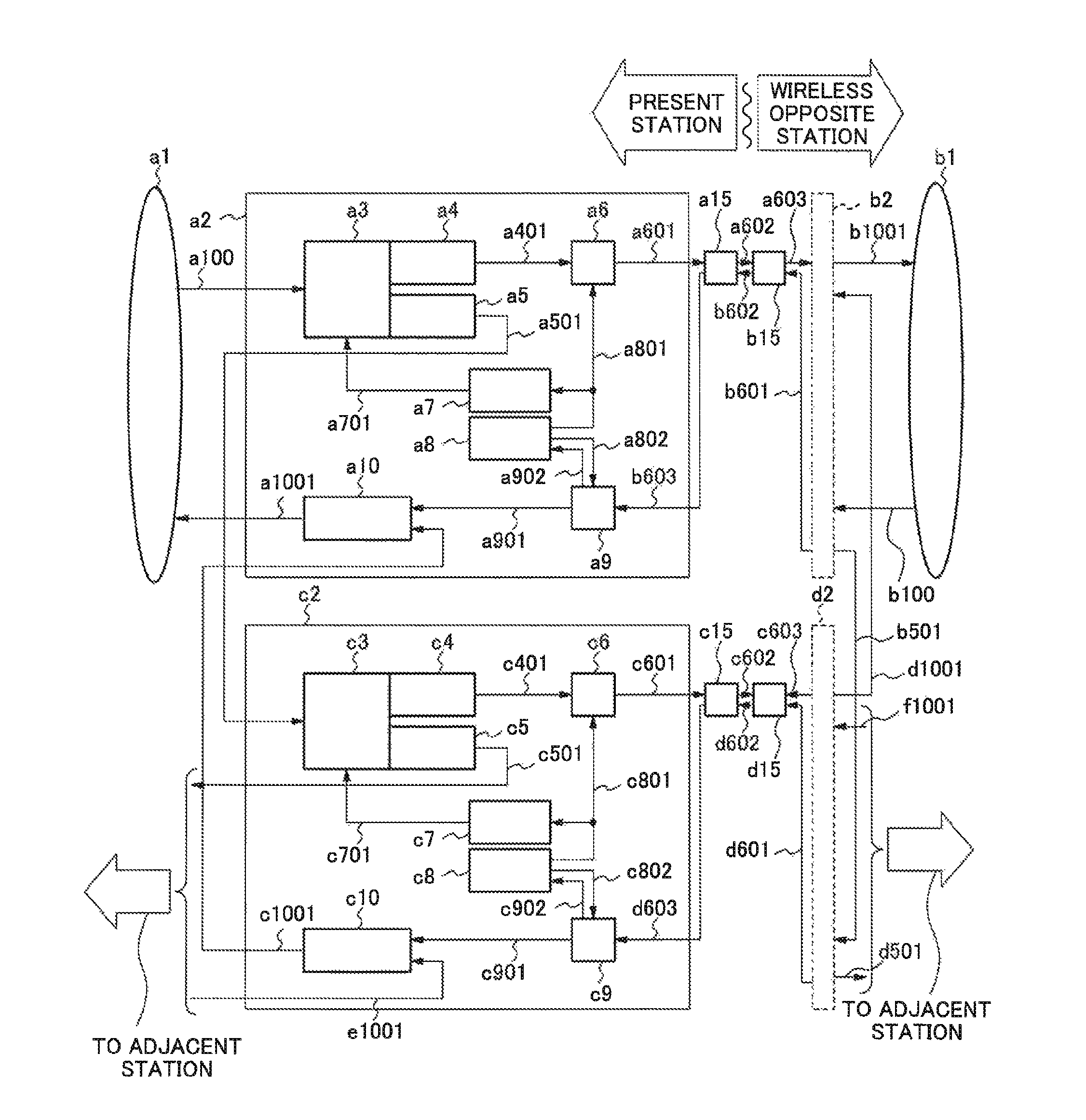
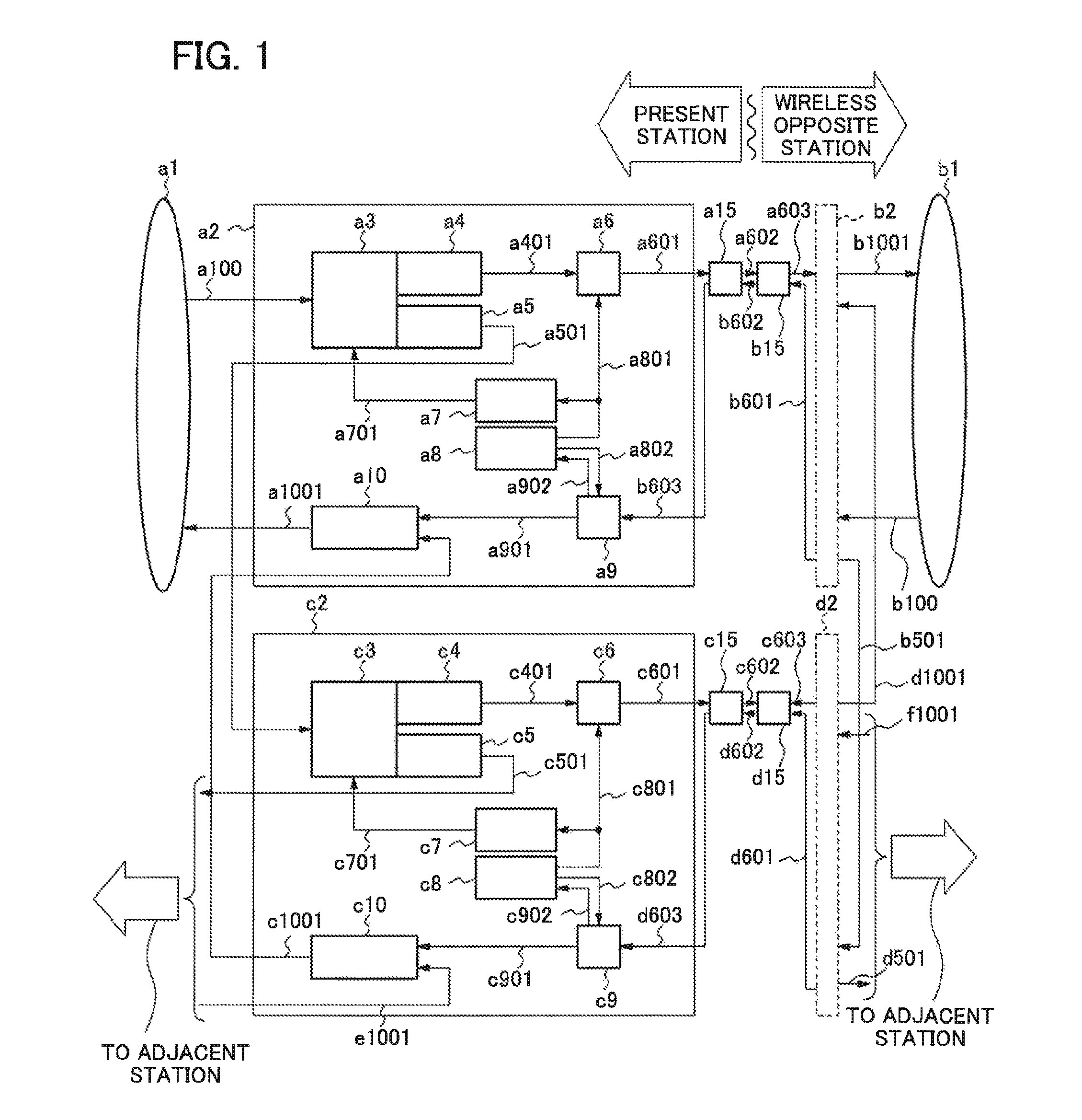
[0048]FIG. 1 is a first diagram illustrating a configuration of a wireless transmission system of a first exemplary embodiment of the invention.

[0049]The wireless transmission system described in FIG. 1 includes user networks a1 and b1, and wireless transmission devices a2, b2, c2 and d2. The user network a1 and the user network b1 exchange data which is composed of a MAC (Media Access Control) frame through the wireless transmission devices each other.

[0050]A configuration of the wireless transmission devices a2 is described below. A configuration of each of the wireless transmission devices b2, c2 and d2 is the same as that of the wireless transmission devices a2. Accordingly, descriptions on the configurations of the wireless transmission devices b2, c2 and d2 are omitted.

[0051]The wireless transmission device a2 includes a frame sorting unit a3, a class A buffer a4, a class B bu...

second exemplary embodiment

[0113]FIG. 4 is a diagram illustrating a configuration of a wireless transmission system of a second exemplary embodiment of the present invention. Wireless transmission devices a21, b21, c21 and d21 in the wireless transmission system of the second exemplary embodiment shown in FIG. 4 differ in the wireless transmission unit and the wireless reception unit which are doubled from the wireless transmission devices a2, b2, c2 and d2 of the first exemplary embodiment in FIG. 1.

[0114]The wireless transmission device a21 is described below as an example. Descriptions thereof are applicable to the wireless transmission devices b21 to d21. The configuration and operations of the part other than the wireless transmission unit and the wireless reception unit are the same as those of the first exemplary embodiment. The inner configuration of the wireless transmission devices b21, c21, and d21 are not shown. The configuration and operations of each of the wireless transmission devices b21, c21...

third exemplary embodiment

[0123]FIG. 5 is a diagram illustrating a configuration of a wireless transmission system of a third exemplary embodiment of the present invention. Wireless transmission devices a22 and b22 in the wireless transmission system of a third exemplary embodiment of FIG. 5 differ in configurations of the wireless transmission unit and the wireless reception unit from the wireless transmission devices a21 and b21 in the second exemplary embodiment in FIG. 4.

[0124]The wireless transmission device a22 is described below as an example. An operation of each part of the wireless transmission device b22 is the same as that of the wireless transmission device a22. A configuration and an operation of the part other than the wireless transmission unit and the wireless reception unit are the same as those of the first exemplary embodiment.

[0125]In the wireless transmission device a22 shown in FIG. 5, the frame sorting unit a3 receives the external input LAN signal a100 from the user network a1. The f...


PUM


Abstract

Disclosed is a transmission device that addresses the issue of alleviating the occurrence of delays in delivery, or the abandonment, of transmitted data in the transmission device when transmission capacity of the transmission device declines, as well as being easy to set up and maintain. The transmission device comprises a sorting means for assigning a first signal to either a first path or a second path on the basis of assignment information for assigning the first signal; a first transmitting means for transmitting the signal from among the first signal that is allocated to the first path upon the first path; and a second transmitting means for transmitting the signal from among the first signal that is allocated to the second path upon the second path.

Description

TECHNICAL FIELD[0001]The invention relates to a transmission device, a transmission method, and a transmission system, in particular a transmission device, a transmission method, and a transmission system which conduct transmission using a plurality of transmission paths.BACKGROUND ART[0002]A method of making a modulation scheme multiple-valued and a method of expanding a wireless band are known as a means for increasing a transmission capacity in a wireless transmission system. As an example of the method of making a modulation scheme multiple-valued, an adaptive modulation scheme is known. A wireless transmission device using the adaptive modulation scheme automatically changes a modulation scheme and a transmission rate depending on a condition of a wireless line. As a result, the wireless transmission device using the adaptive modulation scheme is capable of improving throughput of the wireless transmission system. However, in the adaptive modulation scheme, a modulation scheme ...

Claims


Application Information

Patent Timeline
Patent Type & Authority Patents(United States)
IPC IPC(8): H04L12/26H04J3/14G08C15/00G06F11/00G01R31/08H04L69/14H04L45/24H04L47/41
CPCH04L45/24H04W88/06H04L47/41
Inventor NAKAJIMA, HIROAKI
Owner NEC CORP
Why Eureka
Try Eureka