
Active audio noise cancelling

a technology of active audio and noise cancelling, applied in the field of active audio noise cancelling system, can solve the problems of reducing performance, affecting the performance of parts of the feedback loop that are prone to vary in the transfer function of parts of the feedback loop, and causing destructive interference at least partly cancelling out the nois

Active Publication Date: 2015-02-03
KONINKLIJKE PHILIPS ELECTRONICS NV
View PDF19 Cites 22 Cited by
  • Summary
  • Abstract
  • Description
  • Claims
  • Application Information

AI Technical Summary

Benefits of technology

The invention is about a noise cancellation system that can improve performance without being too complex or difficult to adjust. It does this by compensating for variations in the path from a sound transducer to a microphone by adjusting the feedback means. This can keep the transfer function of the canceling filter constant and result in better noise cancellation. It can also reduce stability constraints for the canceling filter, allowing for a more optimal solution. Overall, this invention can make a noise cancellation system work better and be easier to use in many situations.

Problems solved by technology

Specifically, the noise cancellation signal seeks to provide a signal with an opposite phase of the sound wave arriving at the microphone thereby resulting in a destructive interference that at least partly cancels out the noise in the audio environment.
However, whereas the canceling filter tends to be a fixed, non-adaptive filter in order to reduce complexity and simplify the design process, the transfer functions of parts of the feedback loop tend to vary substantially.
However, although such an approach may ensure stability of the system, it tends to result in reduced performance as the ideal noise canceling function for the specific current secondary path transfer function is not implemented by the canceling filter.

Method used


Image

  • Active audio noise cancelling
  • Active audio noise cancelling
  • Active audio noise cancelling

Examples


Embodiment Construction

[0050]The following description focuses on embodiments of the invention applicable to an audio noise canceling system for a headphone. However, it will be appreciated that the invention is not limited to this application but may be applied to many other applications including for example noise canceling for vehicles.

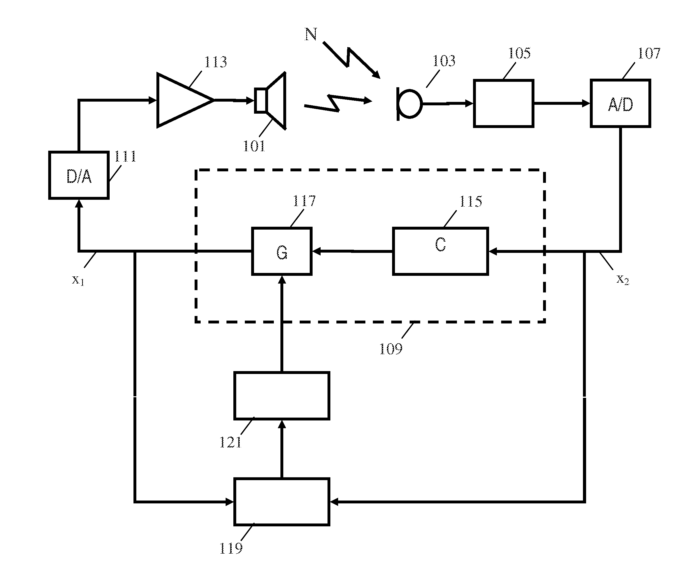
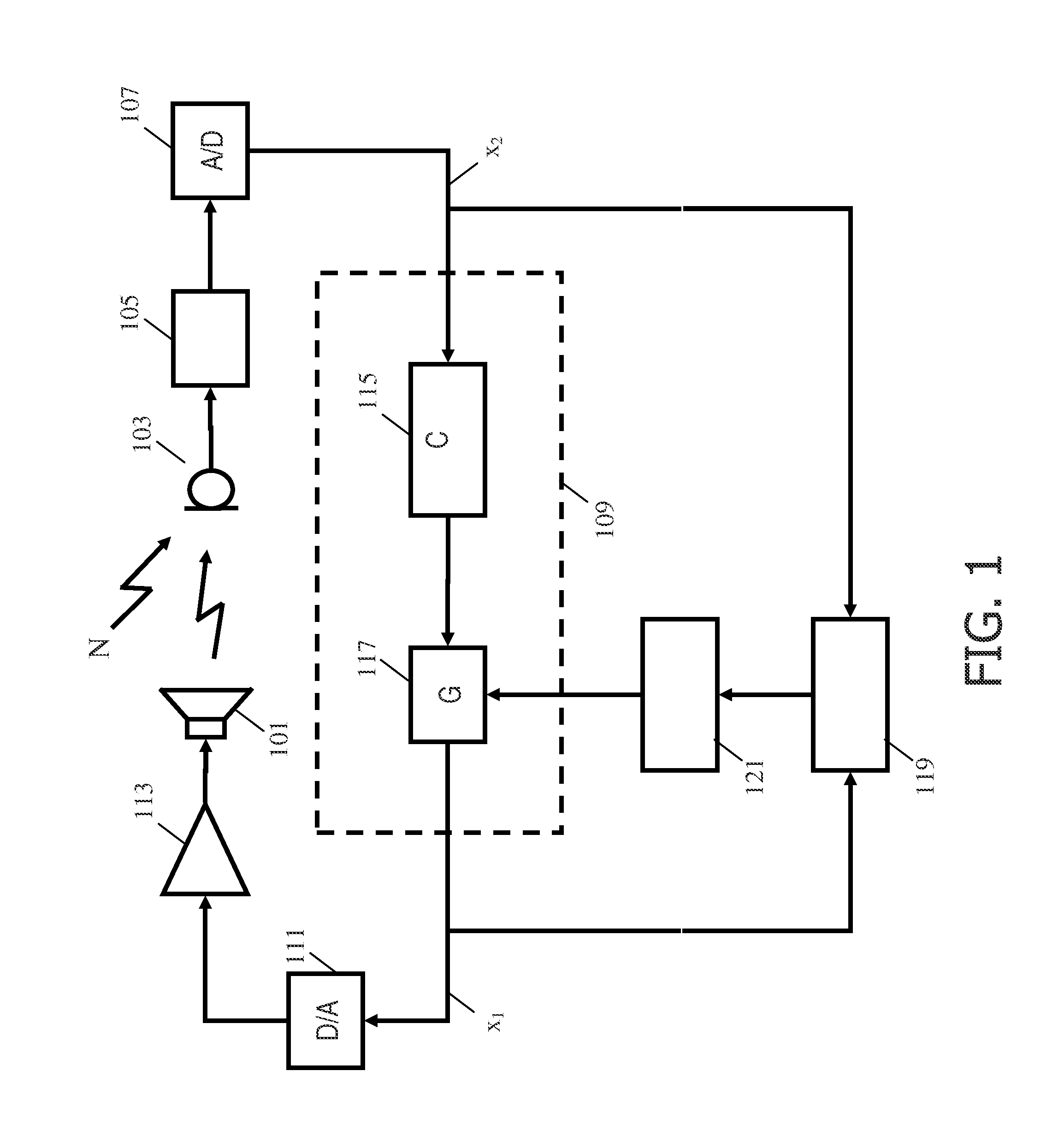
[0051]FIG. 1 illustrates an example of a noise canceling system in accordance with some embodiments of the invention. In the specific example, the noise canceling system is a noise canceling system for a headphone. It will be appreciated that FIG. 1 illustrates the exemplary functionality for one ear and that identical functionality may be implemented for the other ear.

[0052]The noise canceling system comprises a sound transducer which in the specific example is a speaker 101 of the headphone. The system furthermore comprises a microphone 103 which is located close to the user's ear. In the specific example, the headphone may be a circumaural headphone which encloses the...


PUM


Abstract

A noise canceling system comprises a microphone generating a captured signal and a sound transducer radiating a sound canceling audio signal in the audio environment. A feedback path from the microphone to the sound transducer includes a non-adaptive canceling filter and a variable gain and receives the captured signal and generates a drive signal for the sound transducer. A gain detector determines a secondary path gain for at least part of a secondary path of a feedback loop. The secondary path may include the microphone, the sound transducer, and the acoustic path therebetween but does not include the non-adaptive canceling filter or the variable gain. A gain controller adjusts the in of the variable gain in response to the secondary path gain. The system use simple gain estimation and control to efficiently compensate for variations in the secondary path to provide improved stability and noise canceling performance.

Description

FIELD OF THE INVENTION[0001]The invention relates to an audio noise canceling system and in particular, but not exclusively, to an active audio noise canceling system for headphones.BACKGROUND OF THE INVENTION[0002]Active noise canceling is becoming increasingly popular in many audio environments wherein undesired sound is perceived by users. For example, headphones comprising active noise canceling functionality have become popular and are frequently used in many audio environments such as on noisy factory floors, in airplanes, and by people operating noisy equipment.[0003]Active noise canceling headphones and similar systems are based on a microphone sensing the audio environment typically close to the users ear (e.g. within the acoustic volume created by the earphones around the ear). A noise cancellation signal is then radiated into the audio environment in order to reduce the resulting sound level. Specifically, the noise cancellation signal seeks to provide a signal with an op...

Claims


Application Information

Patent Timeline
Patent Type & Authority Patents(United States)
IPC IPC(8): G10K11/16G10K11/178
CPCG10K11/178G10K2210/3026G10K2210/3056G10K11/17817G10K11/17853G10K11/17861G10K11/17875G10K11/17885G10K11/16G10L21/0208G10L21/0232
Inventor VAN LEEST, ADRIAAN JOHAN
Owner KONINKLIJKE PHILIPS ELECTRONICS NV
Learn More