High-voltage multi-level shifter for ultrasound applications and transmit/receive channel for ultrasound applications using said level shifter

a multi-level shifter and ultrasound application technology, applied in pulse generators, pulse automatic control, pulse manipulation, etc., can solve the problems of affecting the later second-harmonic analysis of the reflected echo, generating a second harmonic distortion, and not being stable and accurate, so as to limit the introduction of a second-harmonic asymmetry

Active Publication Date: 2015-02-03
STMICROELECTRONICS INT NV
View PDF3 Cites 3 Cited by
  • Summary
  • Abstract
  • Description
  • Claims
  • Application Information

AI Technical Summary

Benefits of technology

[0037]One embodiment of the disclosure is a high-voltage multi-level shifter for ultrasound applications, that can provide a substantially symmetric transition of the voltage value at its output terminal, to limit the introduction of a second-harmonic asymmetry.
[0039]In one embodiment, which uses, for instance, a shifter with two, three or five levels (or more than five levels), a transmit / receive channel may be obtained, in which switching is carried out by a NMOS transistor for one half and by a PMOS transistor for the other half, which will make the structure inherently symmetrical.
[0040]An advantage of one embodiment of the present disclosure is that the area covered by the shifter is, to a first approximation, equal to that covered by a traditional shifter, and the symmetry of signals is ensured regardless of the supply voltage and, to a first approximation, regardless of the load.
[0041]Finally, another advantage of one embodiment of the present disclosure is that the transmit / receive channel that uses the two-, three- or five-level shifter is self-protected from current recirculation from the output terminal.

Problems solved by technology

Therefore, in classical ultrasonic solutions, the level shifter is obtained using asymmetric output stages (NMOS and PMOS) which inevitably generate a second harmonic distortion.
This asymmetry in the rising or falling edge of the voltage signal to the terminal HVout causes a second harmonic component to be introduced into the emitted signal, and thus disturb later second-harmonic analysis on the reflected echo.
Nevertheless, this optimization is not stable and accurate and especially, with changing operating conditions, it may lead to a considerable degradation of performances, possibly to 10 db lower attenuation of the transmitted second harmonic component.

Method used


Image

  • High-voltage multi-level shifter for ultrasound applications and transmit/receive channel for ultrasound applications using said level shifter
  • High-voltage multi-level shifter for ultrasound applications and transmit/receive channel for ultrasound applications using said level shifter
  • High-voltage multi-level shifter for ultrasound applications and transmit/receive channel for ultrasound applications using said level shifter

Examples


second embodiment

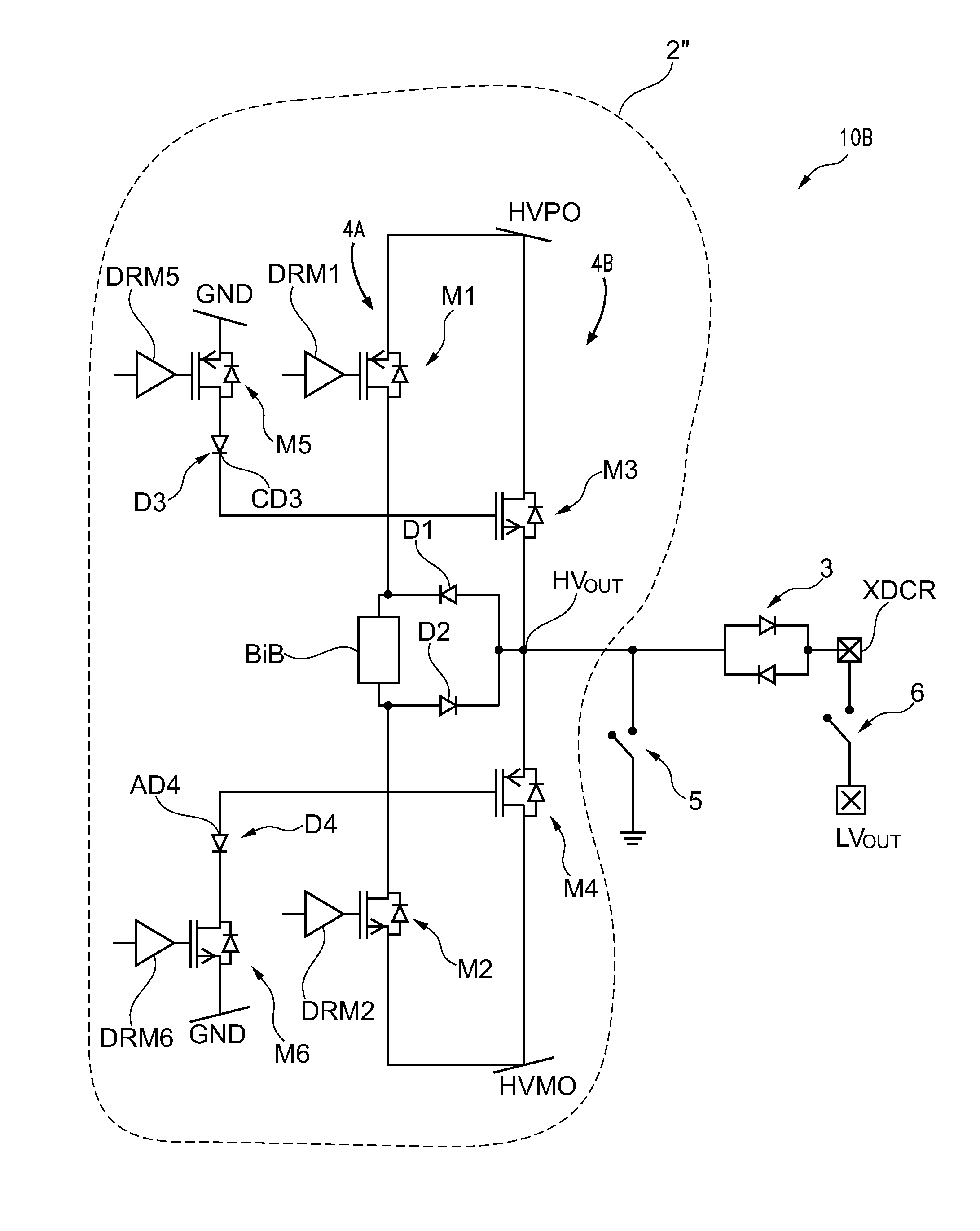
[0091]FIG. 4 shows a transmit / receive channel 10B for ultrasound applications according to the present disclosure, comprising a high-voltage multi-level shifter 2″ for ultrasound applications. The multi-level shifter 2″ is shown to comprise, in addition to the transistors M1-M4, bidirectional battery BiB, diodes D1, D2, and drivers DRM1, DRM2:

[0092]a fifth switching transistor M5 and a third diode D3 coupled in series with each other between a voltage reference terminal having a fixed potential GND, i.e., equal to the ground potential, and the drain terminal of the first transistor M1, and

[0093]a sixth switching transistor M6 and a fourth diode D4 coupled in series with each other between the voltage reference terminal having the fixed potential GND, and the drain terminal of the first transistor M2.

[0094]Particularly, the fifth and sixth switching transistors M5, M6 have respective control terminals connected to and controlled by third DRM5 and fourth DRM6 input drivers.

[0095]It sh...

third embodiment

[0111]FIG. 5 shows a transmit / receive channel 10C for ultrasound applications according to the present disclosure, comprising a high-voltage multi-level shifter 2′″. The multi-level shifter 2′″ is shown to comprise a first branch 4C and a second branch 4D, the first branch 4C including:

[0112]the switching transistors M1, M2;

[0113]the bidirectional battery BiB;

[0114]a fifth diode D5 coupled with the first switching transistor M1, in which a cathode terminal CD5 of the diode D5 is connected with the control terminal of the third switching transistor M3; and

[0115]a sixth diode D6 coupled with the second switching transistor M2, in which an anode terminal AD6 of the sixth diode D6 is connected with said control terminal of said fourth switching transistor M4.

[0116]The multi-level shifter 2′″ comprises a third branch coupled to the first and the second branches and having:

[0117]a seventh switching transistor M7 and a seventh diode D7, coupled in series with each other between a second hi...


PUM


Abstract

A multi-level shifter includes a first branch having first and second transistors coupled between a higher voltage terminal and a lower voltage terminal. The multi-level shifter comprises a second branch, in parallel with the first branch, having: a third transistor, coupled between said higher voltage reference terminal and an output node, a fourth switching transistor coupled between said output node and said lower voltage terminal. Said third and fourth transistors have respective control terminals controlled by drain terminals of said first and second transistors, respectively. The shifter includes a bidirectional battery coupled between said drain terminals of said first and second transistors to supply first and second voltages having the same magnitude and different polarities. Said fourth transistor is controlled according to the first voltage when said first transistor is turned on and said third transistor is controlled according to the second voltage when said second transistor is turned on.

Description

BACKGROUND[0001]1. Technical Field[0002]The present disclosure relates to a multi-level shifter for ultrasound applications and a transmit / receive channel for ultrasound applications using said level shifter.[0003]Particularly, the present disclosure relates to a high-voltage multi-level shifter for ultrasound applications coupled between a connecting terminal and an output terminal of a transmit channel, of the type comprising at least one first and one second communication transistors, coupled in series with each other between the connecting terminal and the output terminal.[0004]The disclosure also relates to a transmission channel of the type comprising at least one high-voltage multi-level shifter as described above, e.g., for use in an ultrasound imaging or ultrasonography.[0005]2. Description of the Related Art[0006]An ultrasound or sonographic machine is known to be a medical diagnostic testing system that uses ultrasonic waves or ultrasounds and is based on the principle of...

Claims


Application Information

Patent Timeline
Patent Type & Authority Patents(United States)
IPC IPC(8): H03L5/00H03K3/356
CPCH03K3/356113H03K5/12H03K19/00361
Inventor GHISU, DAVIDE UGOROSSI, SANDRORICCIARDO, ANTONIO
Owner STMICROELECTRONICS INT NV
Why Eureka
Try Eureka