Methods and systems for adaptive imaging for low light signal enhancement in medical visualization

a low light signal and adaptive imaging technology, applied in the field of medical imaging, can solve the problems of low signal level, limited quantum efficiency and/or deep tissue embedded in the tissue, and the imaging technology used in medical visualization can suffer performance degradation under low light conditions, so as to improve the assessment of relative motion, improve the visualization of low light image signals, and limit the introduction of image artifacts

Active Publication Date: 2020-12-22
STRYKER EUROPEAN OPERATIONS LIMITED
View PDF611 Cites 4 Cited by
  • Summary
  • Abstract
  • Description
  • Claims
  • Application Information

AI Technical Summary

Benefits of technology

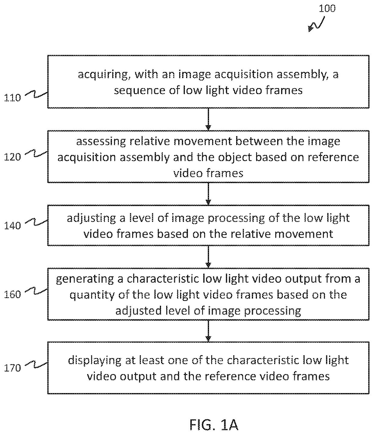
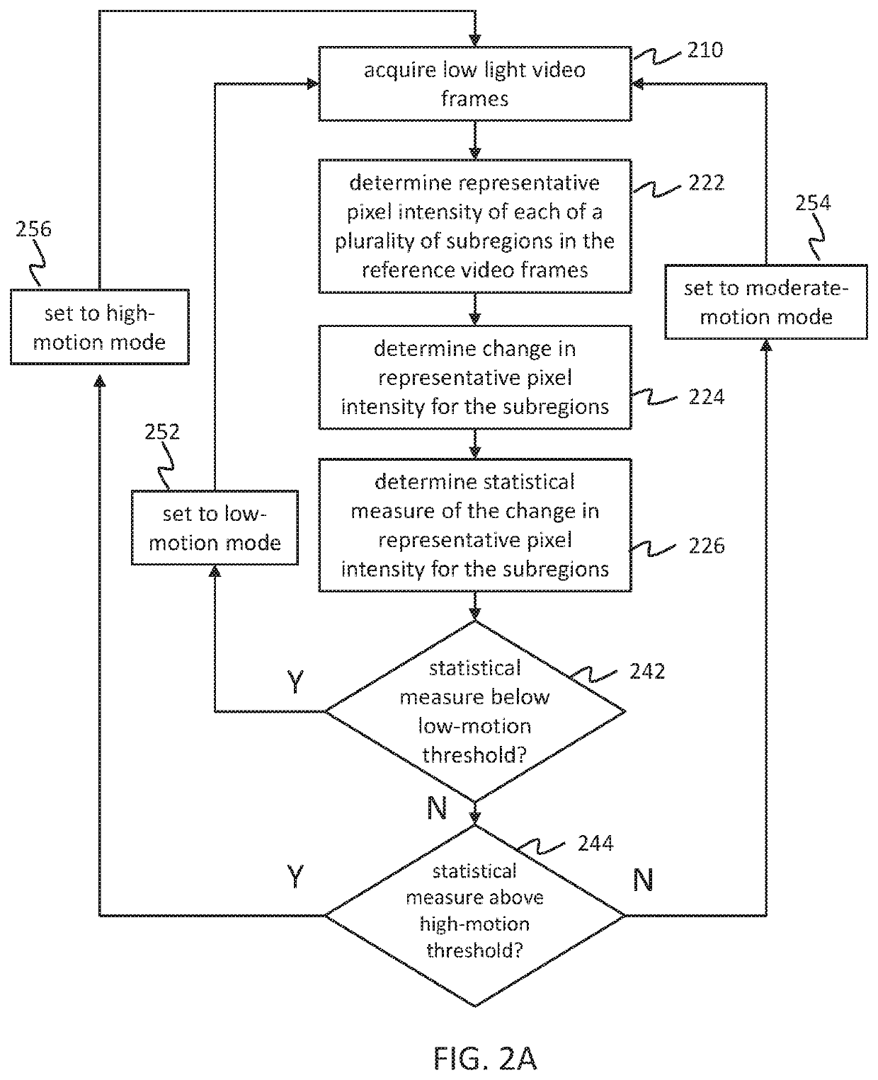
[0010]Such an adaptive imaging method for use in medical imaging may improve visualization of low light image signals from an object while limiting the introduction of image artifacts during relative movement between the image acquisition assembly and the object. In various embodiments, the method may be used when acquiring video of a single low light image signal (e.g. a reflected white light image signal, or a fluorescence image signal) or when acquiring video of a low light image signal while also acquiring video of a relatively higher intensity image signal (e.g. a low light fluorescence image signal and a higher intensity reflected light image signal). In embodiments that include acquiring video of a relatively higher intensity image signal in addition to a low light image signal, the higher intensity image signal may be used as the source of the reference video frames which may provide for improved assessment of relative motion between the image acquisition assembly and the object. In embodiments that include acquiring video of a single low light image signal, that low light image signal may be used as the source of the reference video frames for assessment of relative motion.
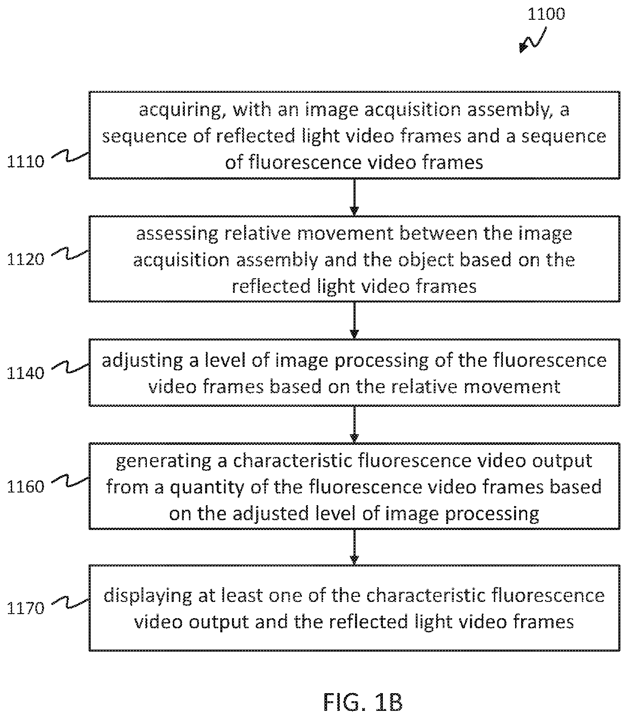
[0023]In any of these embodiments, adjusting the level of image processing of the fluorescence video frames may include adjusting the quantity of fluorescence video frames from which the characteristic fluorescence video output is generated. In any of these embodiments, adjusting the quantity of fluorescence video frames may include setting the quantity of fluorescence video frames to a first predetermined value if the relative movement between the image acquisition assembly and the object is below a first motion threshold. In any of these embodiments, setting the quantity of fluorescence video frames to the first predetermined value may include gradually increasing or decreasing the quantity of fluorescence video frames to the first predetermined value over a series of frames of the characteristic fluorescence video output.

Problems solved by technology

Imaging technology used in medical visualization (e.g., invasive, minimally-invasive, or non-invasive visualization) can suffer performance degradation under low light conditions.
In particular, fluorescence imaging systems used for medical visualization may need to operate with very low emitted signal levels from fluorophores at low concentration, with limited quantum efficiency and / or deeply embedded in the tissue.
Low signal levels are not only problematic in cases of fluorescence imaging, however, but are also known to limit the signal quality of reflected light laparoscopic images which are acquired through small aperture optics (e.g. laparoscopes).
There are occasions, however, when there may be a significant disparity between the intensity levels of the reflected illumination light and the fluorescence light.
However, these workarounds may prove insufficient for acquiring an adequate fluorescence image signal.
In systems that acquire the reflected light image signal and the fluorescence image signal with the same image sensor, providing sufficient compensation for a relatively weak fluorescence image signal becomes particularly challenging.
Furthermore, the reflected light image signal and / or fluorescence image signal may suffer from motion blurring as the result of movement of the imaging system and / or the object being imaged.
Such motion blurring, as well as noise in the reflected light and / or fluorescence image signals, may prevent or hamper the visualization of fine details in the fluorescence images.

Method used


Image

  • Methods and systems for adaptive imaging for low light signal enhancement in medical visualization
  • Methods and systems for adaptive imaging for low light signal enhancement in medical visualization
  • Methods and systems for adaptive imaging for low light signal enhancement in medical visualization

Examples


Embodiment Construction

[0059]Example embodiments will now be described more fully hereinafter with reference to the accompanying drawings; however, they may be embodied in different forms and should not be construed as limited to the embodiments set forth herein. Rather, these embodiments are provided so that this disclosure will be thorough and complete, and will fully convey exemplary implementations to those skilled in the art. Various devices, systems, methods, processors, kits and imaging agents are described herein. Although at least two variations of the devices, systems, methods, processors, kits and imaging agents are described, other variations may include aspects of the devices, systems, methods, processors, kits and imaging agents described herein combined in any suitable manner having combinations of all or some of the aspects described.

[0060]Generally, corresponding or similar reference numbers will be used, when possible, throughout the drawings to refer to the same or corresponding parts.

[...


PUM


Abstract

Adaptive imaging methods and systems for generating enhanced low light video of an object for medical visualization are disclosed and include acquiring, with an image acquisition assembly, a sequence of reference frames and / or a sequence of low light video frames depicting the object, assessing relative movement between the image acquisition assembly and the object based on at least a portion of the acquired sequence of reference video frames or the acquired sequence of low light video frames, adjusting a level of image processing of the low light video frames based at least in part on the relative movement between the image acquisition assembly and the object, and generating a characteristic low light video output from a quantity of the low light video frames, wherein the quantity of the low light video frames is based on the adjusted level of image processing of the low light video frames.

Description

REFERENCE TO RELATED APPLICATIONS[0001]This application claims priority to U.S. Provisional Application Ser. No. 62 / 350,121 filed Jun. 14, 2016, titled “ADAPTIVE IMAGING FOR FLUORESCENCE SIGNAL ENHANCEMENT,” which is hereby incorporated by reference in its entirety.FIELD OF THE INVENTION[0002]The present disclosure relates generally to medical imaging. More specifically, the disclosure relates to adaptive imaging for low light signal enhancement in medical visualization.BACKGROUND OF THE INVENTION[0003]Imaging technology used in medical visualization (e.g., invasive, minimally-invasive, or non-invasive visualization) can suffer performance degradation under low light conditions. In particular, fluorescence imaging systems used for medical visualization may need to operate with very low emitted signal levels from fluorophores at low concentration, with limited quantum efficiency and / or deeply embedded in the tissue.[0004]Low signal levels are not only problematic in cases of fluoresc...

Claims


Application Information

Patent Timeline
Patent Type & Authority Patents(United States)
IPC IPC(8): A61B6/00A61B1/04A61B1/07A61B1/045G02B23/12G06T5/00A61B5/11H04N5/225A61B1/313H04N5/33H04N5/232A61B5/00H04N5/235G06T5/50A61B1/00A61B1/06A61B1/05G16H30/40
CPCA61B1/043A61B1/00009A61B1/0684A61B1/045G06T5/001A61B6/481G16H30/40A61B1/0669H04N5/2354A61B1/07A61B1/05A61B1/0638H04N5/23232H04N5/235A61B5/0071H04N5/332G02B23/12A61B6/5205G06T5/50A61B5/1121A61B2562/0233A61B1/00186G06T2207/10064A61B5/6875A61B2505/05A61B5/6869A61B2576/00G06T2207/20008A61B5/7264A61B1/0646H04N2005/2255G06T2207/30004A61B5/7221A61B1/3132G06T2207/10068A61B2562/0219A61B1/000095A61B1/0655H04N23/555H04N23/951H04N23/74H04N23/11H04N23/70
Inventor FENGLER, JOHN J. P.WESTWICK, PAUL ROALDMOORE, FREDERICK ALLEN
Owner STRYKER EUROPEAN OPERATIONS LIMITED
Why Eureka
Try Eureka