
Stereolithography machine

a stereolithography machine and lithography technology, applied in the field of stereolithography machines, can solve the problems of increasing the number of production rejections, affecting the quality of objects obtained, and not adapting to use, so as to achieve optimal solidification

Active Publication Date: 2015-02-03
DWS SRL
View PDF7 Cites 56 Cited by
  • Summary
  • Abstract
  • Description
  • Claims
  • Application Information

AI Technical Summary

Benefits of technology

The present invention is about a new type of 3D printing machine that can make better solidification results with different types of resin, like hybrid resins. The machine has a special heating system that keeps the resin at the right temperature to prevent separation and get optimal solidification. This heating system also keeps the container and resin in the machine at the same temperature, which makes it easier to maintain. The technical effect of this invention is to improve the quality of 3D printing.

Problems solved by technology

The applicant for the present patent has found out that the known machines of the type described above pose the drawback that they don't adapt to the use of the so-called “hybrid” resins, which contain various components of different types like, for example, a plastic component mixed with ceramics, wax or another non-plastic component.
Therefore, there is the inconvenience that the use of the above mentioned hybrid resins in the machines of known type negatively affects the quality of the objects obtained and increases the number of production rejects.

Method used


Image

  • Stereolithography machine
  • Stereolithography machine
  • Stereolithography machine

Examples


Embodiment Construction

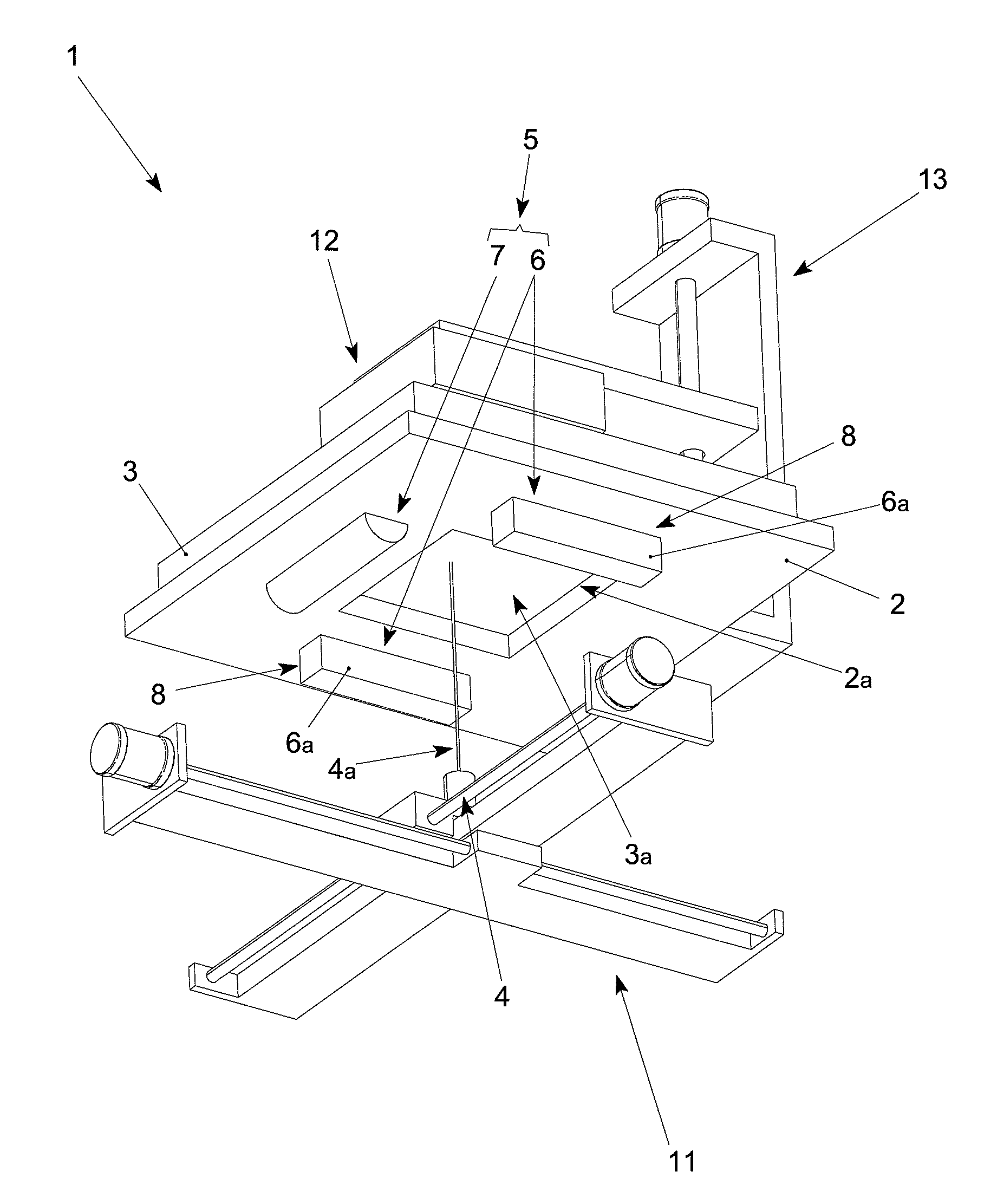
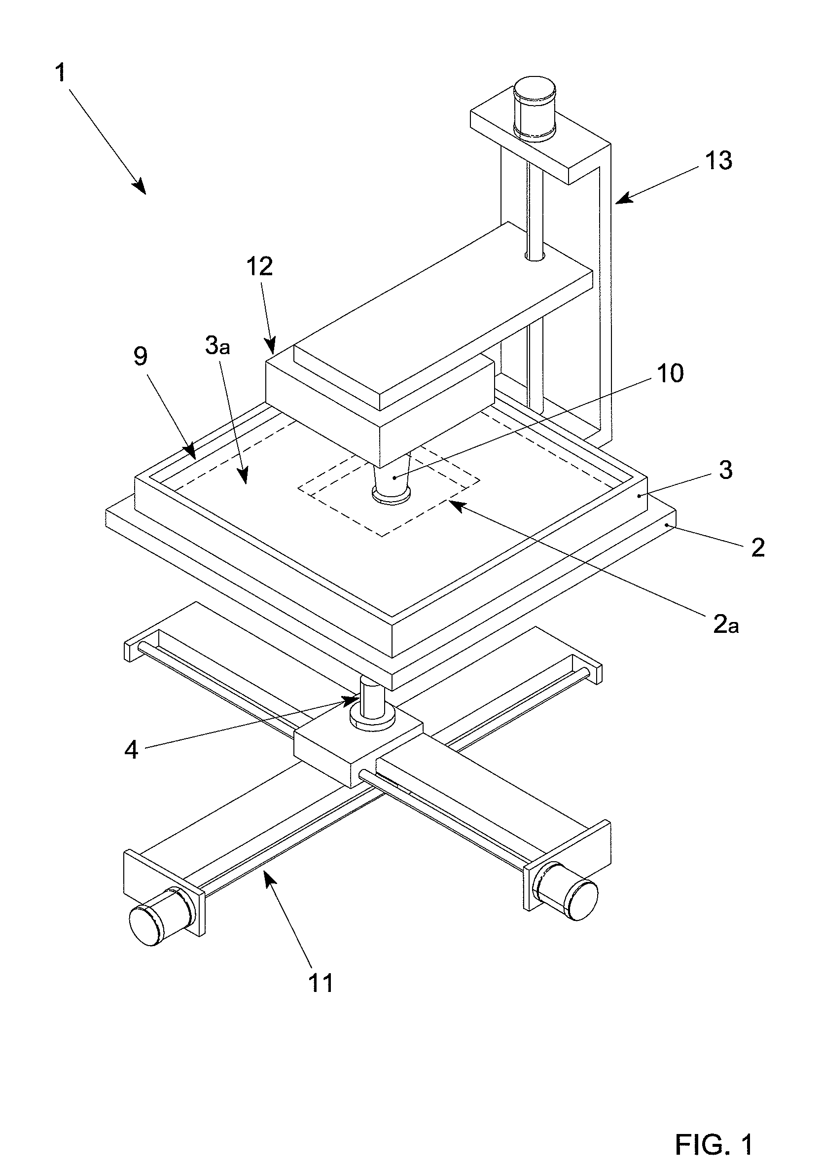
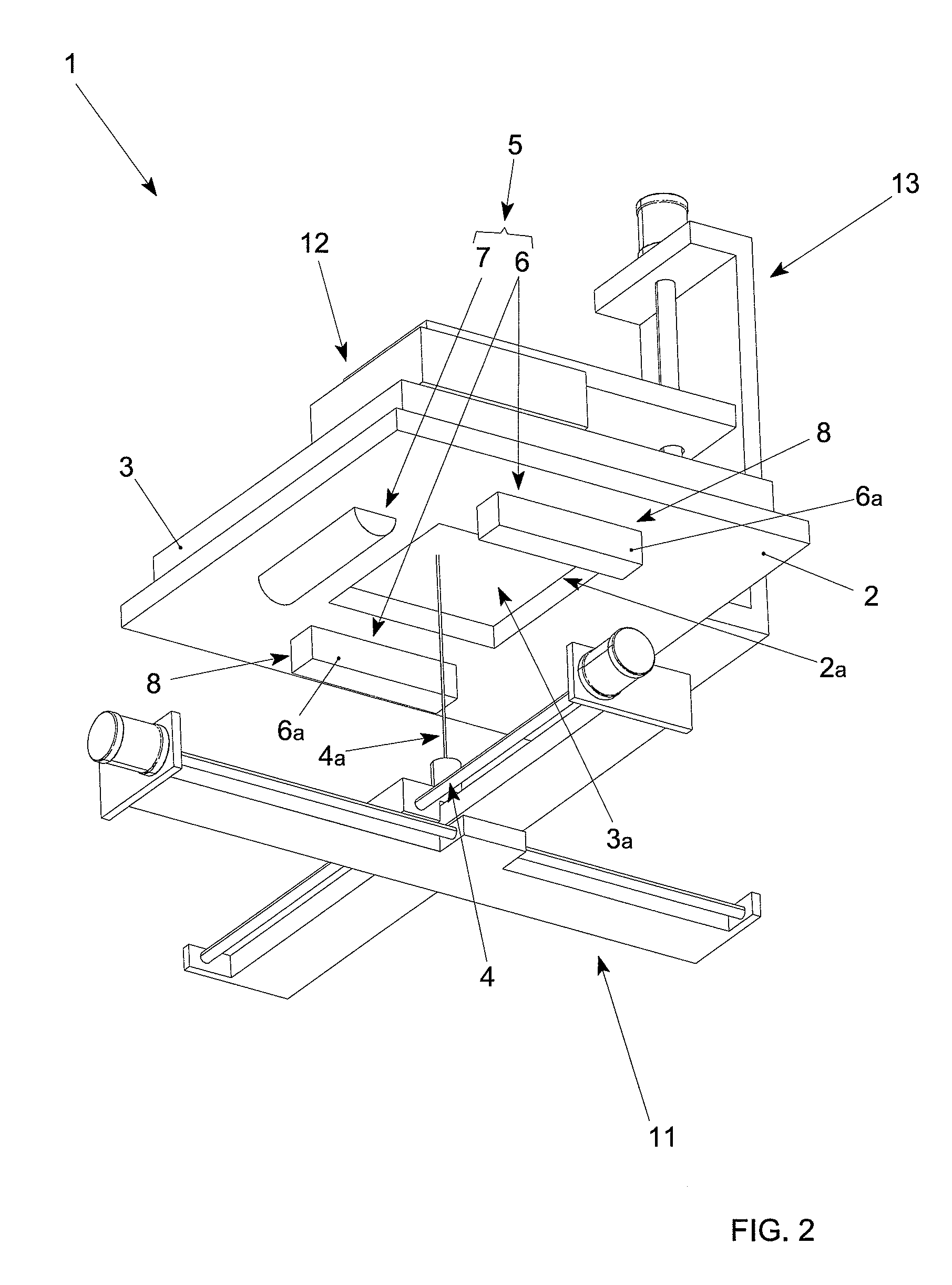
[0023]The stereolithography machine of the invention, indicated as a whole by 1 in FIG. 1, comprises a support plate 2 associated with a container 3 suited to contain a liquid substance, in particular a liquid resin 9, and provided with a transparent bottom 3a.

[0024]Furthermore, as shown in FIG. 2, there is a radiation source 4 arranged below the support plate 2, whose radiation is suited to solidify the resin 9 or another equivalent liquid substance.

[0025]The radiation source 4 conveys a radiation beam towards the container 3 through a hole 2a provided in the support plate 2, thus causing the solidification of the resin layer 9 adjacent to the bottom of the container 3.

[0026]The radiation source 4 preferably but not necessarily emits a laser beam 4a and is associated with an operating unit 11 suited to shift the point of incidence of the laser beam 4a on the container 3 with respect to two mutually orthogonal axes.

[0027]It is evident, on the other side, that in construction varian...


PUM

PropertyMeasurementUnit
transparentaaaaaaaaaa
temperatureaaaaaaaaaa
homogeneous heat distributionaaaaaaaaaa

Abstract

The invention is a stereolithography machine (1) comprising the following: a support plate (2) provided with a hole (2a); a container (3) associated with the support plate (2) and comprising a transparent bottom (3a); a radiation source (4) arranged below the support plate (2) and suited to convey a radiation beam towards the transparent bottom (3a) through the hole (2a); a temperature control unit (5) suited to maintain the support plate (2) at a predetermined temperature.

Description

FIELD OF THE INVENTION[0001]The present invention concerns a stereolithography machine particularly suited to quickly prototype three-dimensional objects.BACKGROUND OF THE INVENTION[0002]A stereolithography machine of known type comprises a transparent container supported by a plate provided with a central opening, on the underside of which there is a light emitter.[0003]The container contains a plastic resin that polymerizes and, therefore, solidifies, if exposed to the radiation emitted by said emitter that is preferably a laser emitter.[0004]On top of the container there is a support element to which the three-dimensional object remains anchored during its formation.[0005]As is known, the manufacturing process of the three-dimensional object takes place by selectively solidifying a thin layer of resin adjacent to the bottom of the container through the action of the laser beam that reaches said resin layer through the hole present in the plate and the transparent bottom.[0006]The...

Claims


Application Information

Patent Timeline
Patent Type & Authority Patents(United States)
IPC IPC(8): B29C35/08B29C41/02B29C67/00
CPCB29C67/0066B29C67/0088B29C67/0085B29C64/135B29C64/295B29C64/393B29C35/08B29C67/00
Inventor ZENERE, SERGIO
Owner DWS SRL
Learn More