Effluent containment device

a technology of effluent containment and discharge pipe, which is applied in mechanical equipment, transportation and packaging, valve types, etc., can solve the problems of seepage containment space within the drainage device, and achieve the effect of facilitating transfer and enhancing gravity

Active Publication Date: 2015-02-03
EARP DANNY
View PDF13 Cites 3 Cited by
  • Summary
  • Abstract
  • Description
  • Claims
  • Application Information

AI Technical Summary

Benefits of technology

[0004]The present invention is a disposable drain device intended for use as a means to constrain a material (typically a fluid) that seeps or spills from a pipe-joint coupling as the coupling is disassembled. The material that seeps from the pipe-joint coupling as the coupling components are separated is constrained within the interior space of the drain device and directed to a drain means to allow the seepage to be cleanly collected (i.e., without spillage into the environment, or excessive atomization) in an appropriate waste container. This is important, because it allows the present disposable drain device to be practiced on pipe-joint couplings of conduits that contain hazardous materials, for which materials the exposure to and the disposal of are regulated by one or more governmental agencies. Additionally, after use, the present drain device can be disposed of as solid waste, rather than needing to be cleaned—which creates an additional waste stream of the cleaning effluent if the seepage was a hazardous material. Therefore, the drain device being “disposable” is a feature of the present invention that allows the avoidance of creating an additional hazardous waste stream.
[0006]The drain means is disposed on the wrap member, allowing seepage material collected in the containment space to be eliminated by the force of gravity. Seepage from the conduit can be accumulated in the interior space of the drain device or removed continuously. The center of the drain means is disposed proximate the middle portion of the wrap member. The drain means has a drain port passing through the surfaces of the wrap member. Preferentially, the drain means also has a drain neck in flow communication with the drain port, with an inlet portion and an outlet portion. The drain port directly connects to the inlet of the drain neck. The drain neck is adapted to direct seepage material out of the installed wrap member and facilitates transferring it to another vessel (not shown) for disposal. The drain neck not only serves to allow a user to more readily direct the seepage material effluent into the other vessel (for disposal), but can also serve to enhance the effect of gravity depending on the relative length of the drain neck.

Problems solved by technology

This creates a seepage containment space within the drainage device.

Method used


Image

  • Effluent containment device
  • Effluent containment device
  • Effluent containment device

Examples


Embodiment Construction

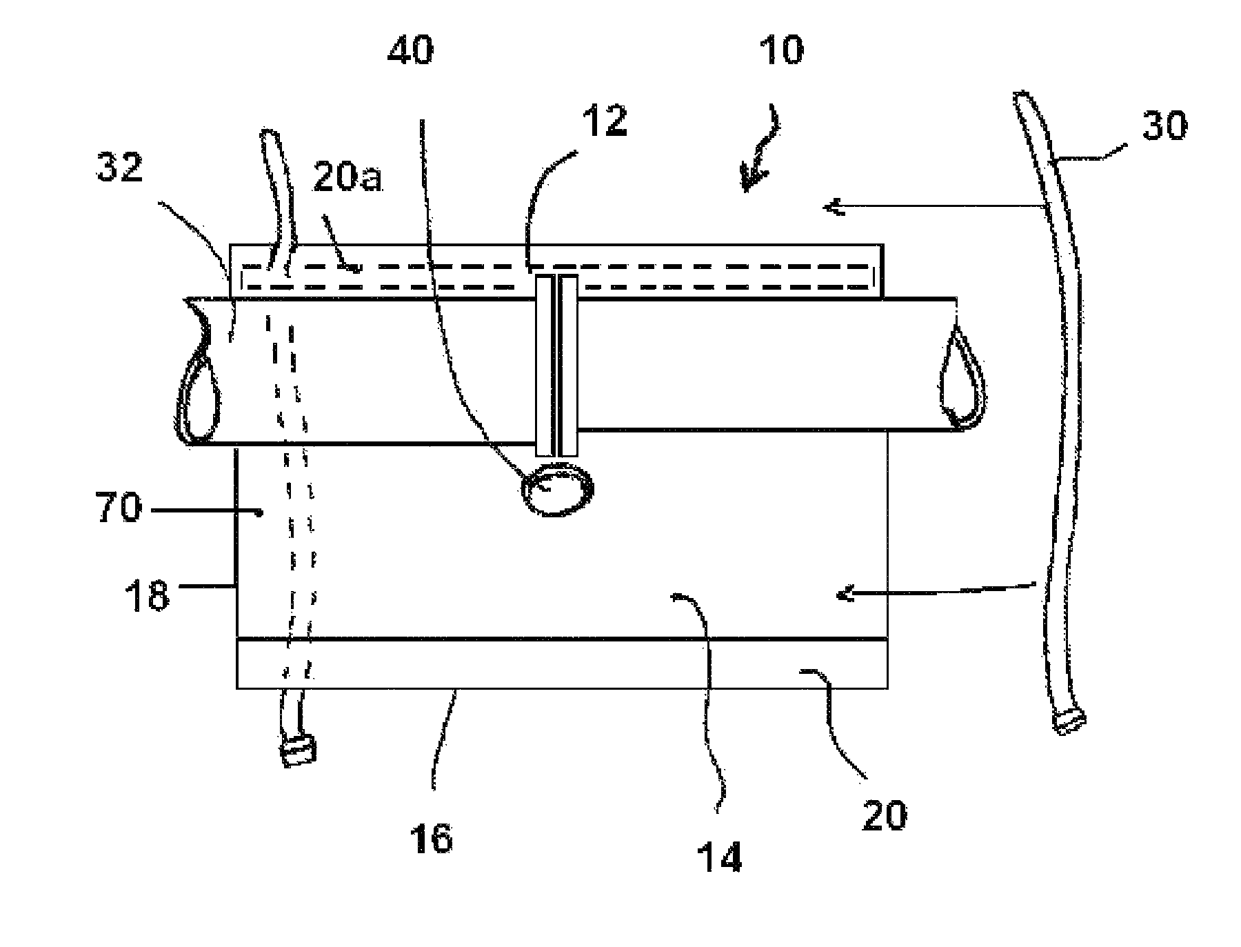
[0011]The present invention is a disposable device for containing and directing the outflow or seepage of the contents of a conduit, such as a pipe, which is discharged from a pipe-joint coupling when the coupling components (e.g., coupling flanges) are separated. Referring now to the drawings, the details of preferred embodiments of the present invention are graphically and schematically illustrated. Like elements in the drawings are represented by like numbers, and any similar elements are represented by like numbers with a different lower case letter suffix.

[0012]As illustrated in FIG. 1A, the disposable drain device 10 of the present invention is intended for use as a means to constrain the material (typically a fluid) that seeps or spills from a pipe-joint coupling 12 as the coupling 12 is disassembled. The appropriate types of pipe-joint couplings 12 on which the present disposable drain device 10 is intended to be practiced are selectable by one of ordinary skill in the art i...


PUM


Abstract

Disclosed is a disposable drain device for containing seepage from a pipe-joint coupling as the coupling is broken open. The drain device has a wrap member made of a sheet material sufficiently pliant to be wrapped around the circumference of the pipe-joint coupling and resistant to the seepage composition. A drain means is disposed on the wrap member, having a drain port passing through the surfaces of the wrap member and a drain neck. The drain neck is disposed to direct seepage out of the installed wrap member. After use, the drain device can be disposed of as solid waste, rather than needing to be cleaned if the seepage was a hazardous material. The drain device being “disposable” allows the avoidance of creating an additional hazardous waste stream.

Description

[0001]The present application claims the benefit of prior filed U.S. Provisional Patent Application Ser. No. 60 / 989,377, filed 20 Nov. 2007, to which the present application is a regular U.S. national application.FIELD OF THE INVENTION[0002]The present invention is in the field of apparatuses for containment of effluent from conduits. More specifically, the present invention relates to a transportable device for collecting effluent from conduits when the conduit couplings or flanges are separated.BACKGROUND OF THE INVENTION[0003]In the petrochemical and other industries, it is necessary at certain times to disassemble pipe-joint couplings. When this occurs, a material (typically a fluid) seeps or spills from the pipe-joint coupling as the coupling is disassembled. A typical method to collect this discharge from the uncoupled pipe-joint has been to allow the discharge material to drain into a bucket or other container under the disassembled coupling. However, because this discharge c...

Claims


Application Information

Patent Timeline
Patent Type & Authority Patents(United States)
IPC IPC(8): F16L55/168B08B17/00B08B17/02F16L55/07
CPCF16L55/07B08B17/00B08B17/025Y10T137/5835
Inventor EARP, DANNY
Owner EARP DANNY
Why Eureka
Try Eureka