Microbubble-generating apparatus

Active Publication Date: 2015-01-27
TAIKOHGIKEN CO LTD
View PDF11 Cites 5 Cited by
  • Summary
  • Abstract
  • Description
  • Claims
  • Application Information

AI Technical Summary

Benefits of technology

The patent text describes a need for a microbubble generating apparatus that is portable, simple to operate and can generate a large amount of microbubbles efficiently. The invention aims to address this problem by providing a more efficient, portable microbubble generating apparatus.

Problems solved by technology

In this case, a technique of generating air bubbles in water with a common aeration system is conventionally used; however, a large-scale high-cost system is required for maintaining an amount of dissolved oxygen in an object water area at a necessary level.
As a system becomes larger in scale, it is not easy to move the system to a desired location and the system lacks mobility and operability.

Method used


Image

  • Microbubble-generating apparatus
  • Microbubble-generating apparatus
  • Microbubble-generating apparatus

Examples


Embodiment Construction

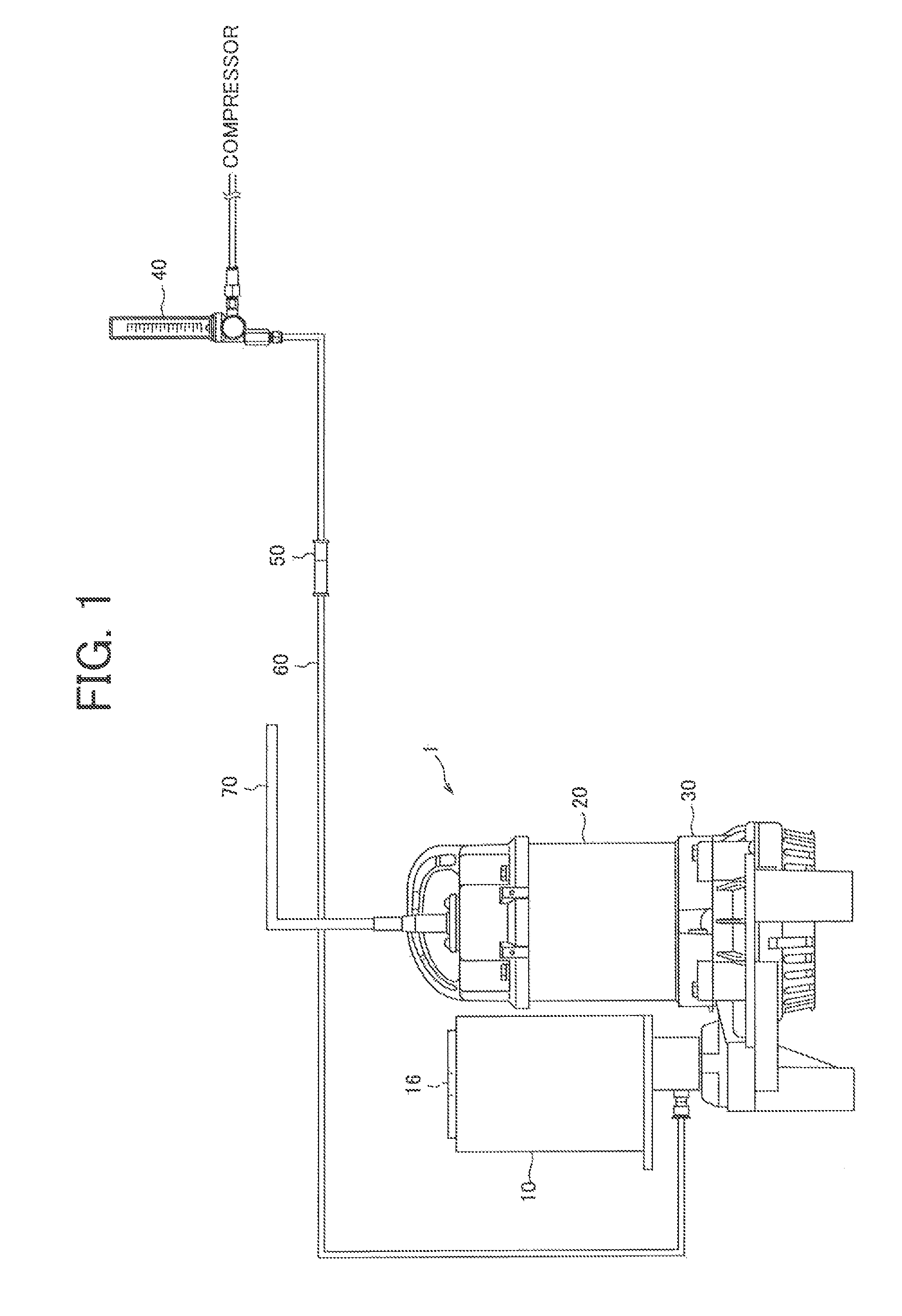
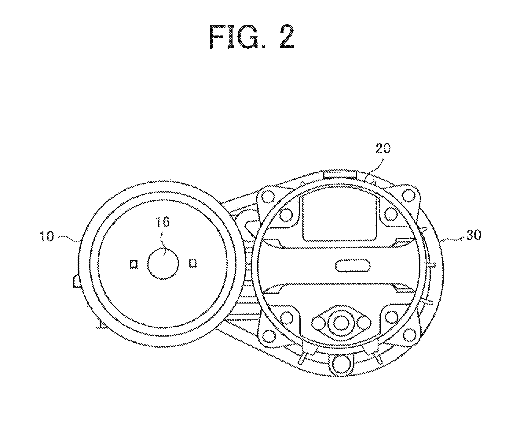
[0028]FIGS. 1 and 2 are diagrams for explaining an exemplary system configuration to which a microbubble generating apparatus according to the present invention is applied. A system of FIG. 1 represents an exemplary configuration of a system utilized in a location with a relatively deep water depth (e.g., water depth on the order of 5 to 12 m) such as a fish farm on the sea, for example. FIG. 2 is a schematic of a top surface of a microbubble generating apparatus 1 depicted in FIG. 1.

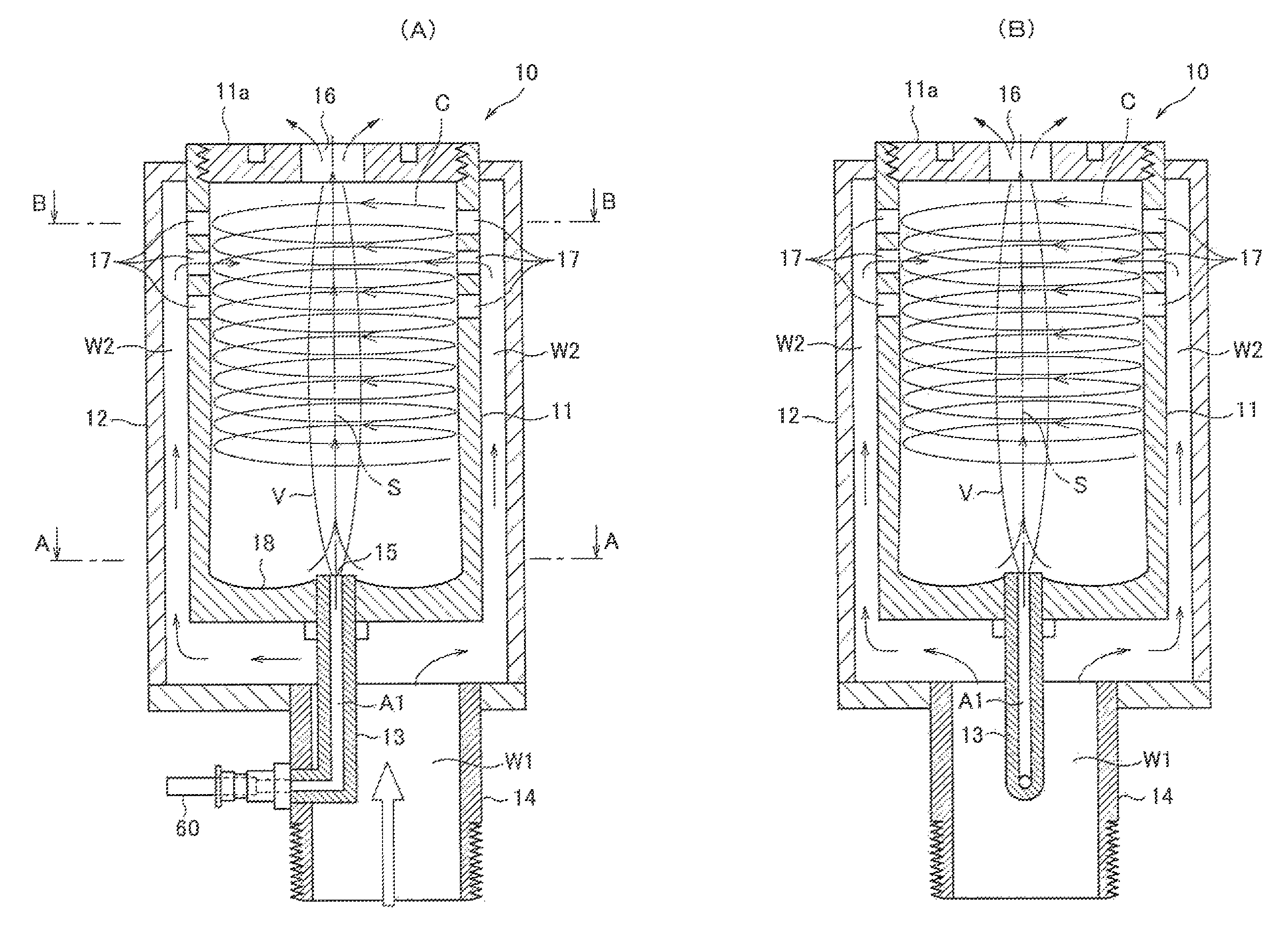
[0029]The microbubble generating apparatus 1 includes a microbubble generator 10 generating microbubbles in liquid and discharging the microbubbles to the outside of the generator, a waterproof pump 20 for sucking and pumping surrounding liquid (seawater in the case of a marine fish farm) into the microbubble generator 10, and an electric motor 30 for driving the pump 20 and is formed by integrally configuring the microbubble generator 10, the pump 20, and the electric motor 30.

[0030]The microbubble gen...


PUM

PropertyMeasurementUnit
Pressureaaaaaaaaaa

Abstract

The micro bubble generator comprises a gas-liquid generating tank and an outer shell tank and the space there between is configured as a channel for the liquid. A plurality of liquid supply ports are provided in the channel and supply liquid through the channel into the gas-liquid generating tank from the liquid supply ports. Inside the gas-liquid generating tank, a swirling flow is generated by the supplied liquid and a negative pressure cavity is thereby generated near the axis of the cylinder axis. From the gas supply portion, gas is supplied from the outside by the action of the negative pressure cavity or by additionally forcing the gas supply. The supplied gas is formed into micro hubbies by the swirling liquid flow and is discharged from the gas-liquid outlet discharging port as a gas-liquid.

Description

TECHNICAL FIELD[0001]The present invention relates to a microbubble generating apparatus generating microbubbles in liquid.BACKGROUND OF THE INVENTION[0002]A utilization technique of fine bubbles called microbubbles having a diameter of several tens of μm to several μm is attracting attention, in industrial fields. A system including a multiplicity of fine bubbles in liquid has a much greater bubble surface area as compared to a system including a single bubble having the same volume and a residence time of fine bubbles in water etc., is also longer. This enables improvements in the dissolution characteristics of gas into fine bubbles, the characteristics of adsorption of impurities in liquid by fine bubbles, etc., thereby increasing the substance transport effect. A technique of microbubbles is applied in various industrial fields such as fish and shellfish culture, wasterwater treatment, chemical reactors, medical care, and plant cultivation, for example.[0003]An apparatus using a...

Claims


Application Information

Patent Timeline
IPC IPC(8): B01F3/04B01F5/00
CPCB01F3/04106B01F3/04503B01F5/0062B01F5/0071B01F2003/04858B01F23/23231B01F23/2323B01F23/2373B01F25/1041B01F25/102B01F23/20B01F25/00B01F35/71B01F23/231
Inventor TAKASE, ICHIROTSUTSUMI, HIROAKI
Owner TAIKOHGIKEN CO LTD
Why Eureka
Try Eureka