
Stock feeder for woodworking equipment

a technology for woodworking equipment and stock feeders, applied in the field of stock feeders, to achieve the effect of high dust resistance and high heat dissipation efficiency

Active Publication Date: 2015-01-13
HSIUNG TAI YUAN
View PDF3 Cites 15 Cited by
  • Summary
  • Abstract
  • Description
  • Claims
  • Application Information

AI Technical Summary

Benefits of technology

The present invention is about a woodworking equipment stock feeder that is designed to be highly efficient in heat dissipation and prevent dust from getting inside its system. The feeder has a separate power fan that is independent of the main electric unit, which ensures optimal heat dissipation efficiency even at low speeds. Furthermore, each feed wheel set has its own casing to keep out foreign matter and prevent the chains from getting stuck. These features make the feeder more reliable and durable, improving its overall performance and efficiency.

Problems solved by technology

Furthermore, power is transmitted to the wheels of each feed wheel set by chains, which feature stabler power transmission and longer service lives than belts.

Method used


Image

  • Stock feeder for woodworking equipment
  • Stock feeder for woodworking equipment
  • Stock feeder for woodworking equipment

Examples


Embodiment Construction

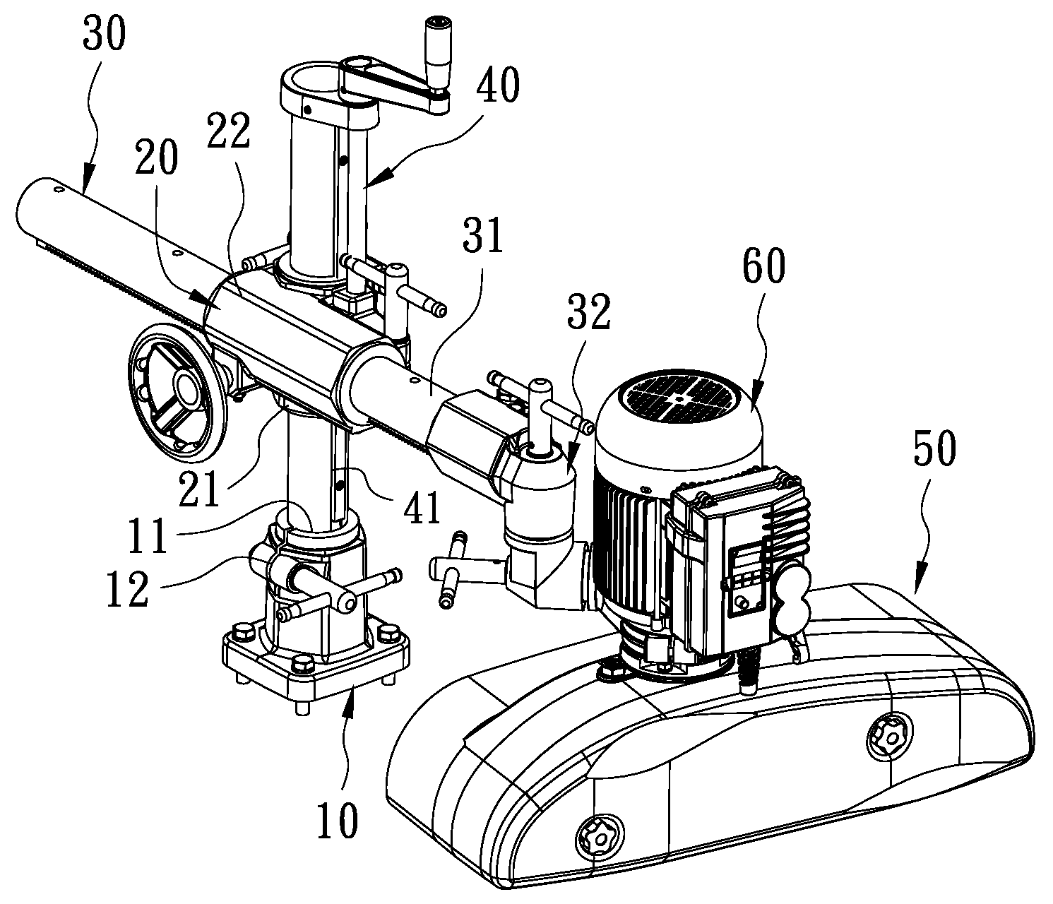
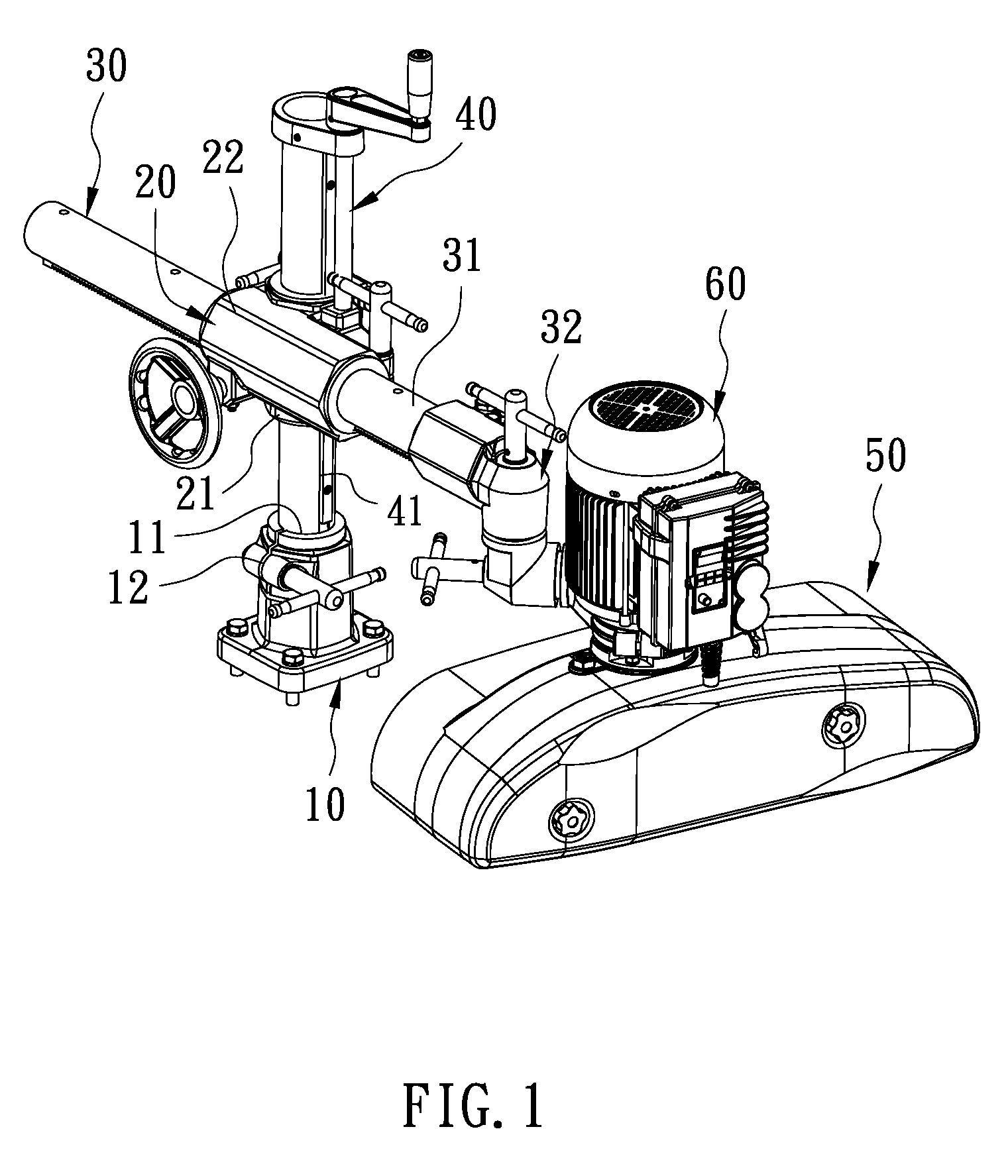
[0028]In one embodiment of the present invention as shown in FIG. 1, a stock feeder for woodworking equipment includes a base 10, a cross clamp 20, a horizontal bar unit 30, a vertical bar unit 40, a feeding unit 50, and an electrical unit 60.

[0029]The base 10 includes an insertion groove 11 and an opening 12 extending along the groove wall of the insertion groove 11.

[0030]The cross clamp 20 includes a vertical clamping sleeve 21 and a horizontal clamping sleeve 22 which are arranged in a cross shape.

[0031]The horizontal bar unit 30 includes a horizontal bar 31 extending through the horizontal clamping sleeve 22 and a clamp assembly 32 mounted at one end of the horizontal bar 31. The clamp assembly 32 connects the horizontal bar 31 to the electrical unit 60 and the feeding unit 50 and is configured for adjusting the working angle of the feeding unit 50.

[0032]The vertical bar unit 40 includes a vertical bar 41 extending through the vertical clamping sleeve 21.

[0033]Referring to FIG. ...


PUM


Abstract

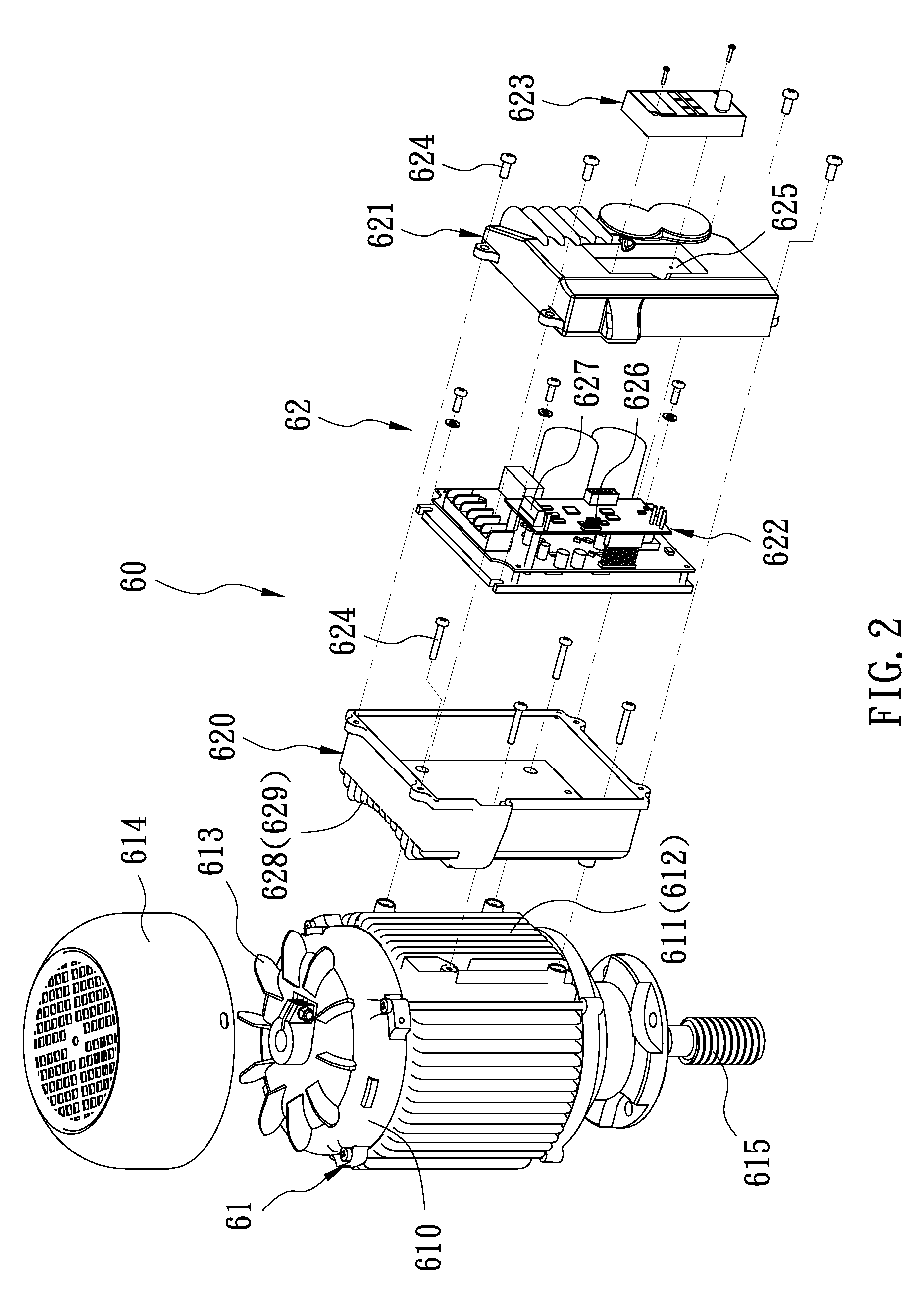
A stock feeder for woodworking equipment includes a base, a cross clamp, a horizontal bar unit, a vertical bar unit, a feeding unit, and an electrical unit. The electrical unit has an electrical unit main body and a variable-frequency drive. The electrical unit main body has a first housing, a plurality of heat dissipation grooves provided on the outer periphery of the first housing, and a power fan which is independently mounted on a top portion of the first housing and in communication with the heat dissipation grooves. The variable-frequency drive has a second housing, a variable-frequency circuit sealed in the second housing, and a control panel exposed outside the second housing. The second housing has an outer surface provided with a plurality of heat dissipation slots corresponding in position to and in communication with the heat dissipation grooves of the electrical unit main body.

Description

BACKGROUND OF THE INVENTION[0001]1. Technical Field[0002]The present invention relates to a stock feeder and, more particularly, to a stock feeder configured for woodworking equipment and featuring both high dust-tightness and high heat-dissipation efficiency.[0003]2. Description of Related Art[0004]Generally, a stock feeder is used in a woodworking process to feed and hold steady the wood board being worked on. An existing stock feeder typically includes a base disposed on a workbench, a vertical bar inserted in the base, a clamp mounted around the vertical bar, a horizontal bar extending through the clamp and held perpendicular to the vertical bar, a feeding unit pivotally connected to one end of the horizontal bar, and an electrical unit provided on the feeding unit. The bottom portion of the feeding unit is provided with a plurality of feed wheels for holding down a board. The electrical unit has a motor for driving the feed wheels into rotation, a fixing mount provided on the h...

Claims


Application Information

Patent Timeline
Patent Type & Authority Patents(United States)
IPC IPC(8): B27B25/00B27C1/12B27B25/02B27B25/06B27B25/10B27B31/00H02K5/18H02K9/06H02K11/00
CPCH02K11/0073B27B25/10B27B31/003H02K5/18B27B25/02H02K9/06B27B25/06H02K11/33
Inventor HSIUNG, TAI-YUAN
Owner HSIUNG TAI YUAN
Learn More