
N port fiber optical switch

a fiber optic switch and fiber optic technology, applied in optics, instruments, optical light guides, etc., can solve the problems of limited optical power handling in these systems, many of the optical elements required for polarization and interference switches have limited applicability or are not available, and the switching application of broadband optical signals is limited. , to achieve the effect of reducing switching time, short switching time and maintaining mechanical simplicity

Active Publication Date: 2015-01-06
UNITED STATES OF AMERICA
View PDF3 Cites 3 Cited by
  • Summary
  • Abstract
  • Description
  • Claims
  • Application Information

AI Technical Summary

Benefits of technology

The invention is a new switch that solves problems in previous designs by using a system that always works symmetrically to the number of ports. The switch has fast switching times and can handle strong signals. It can be used for broad-band and high-power optical signal routing, and can have a large number of ports. The switch's fiber movement is based on 3D space, which allows it to easily connect and switch between a variable number of ports.

Problems solved by technology

Fiber optical systems involving physical effects such as polarization, birefringence, refraction and interference are sensitive to the optical wavelength and therefore manifest significant limitations in broadband optical signal switching applications.
In particular for applications where the optical wavelength lies beyond the near infrared optical spectrum, including the mid-wave and long-wave infrared, many of the optical elements required for the polarization and interference switches have limited applicability or are not available.
Fiber optical systems based on the movement of fiber for direct end-to-end fiber coupling or imaging-type systems including reflective mirror-type approaches are not as sensitive to the wavelength of light providing a viable alternative for broadband applications.
Optical power handling in these systems is limited by the optical coating and the size of the optical elements used.
Systems based on the movement of fibers such as end-to-end fiber coupling are power limited only by the maximum power handling of the optical fiber transmitting the signal.

Method used


Image

  • N port fiber optical switch
  • N port fiber optical switch
  • N port fiber optical switch

Examples


Embodiment Construction

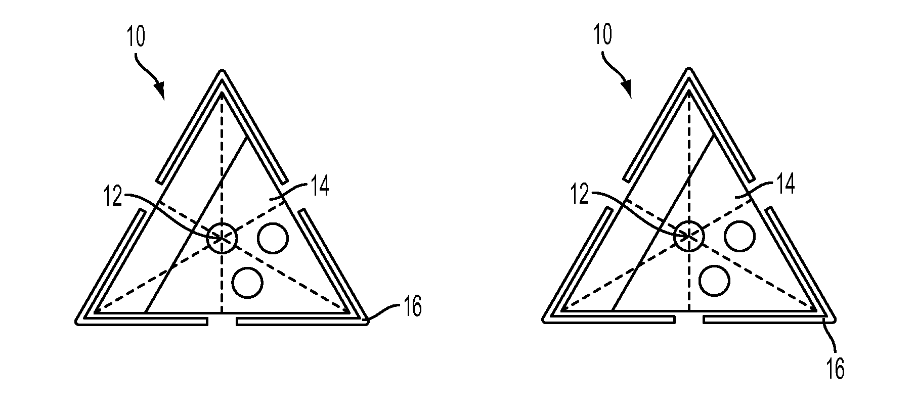
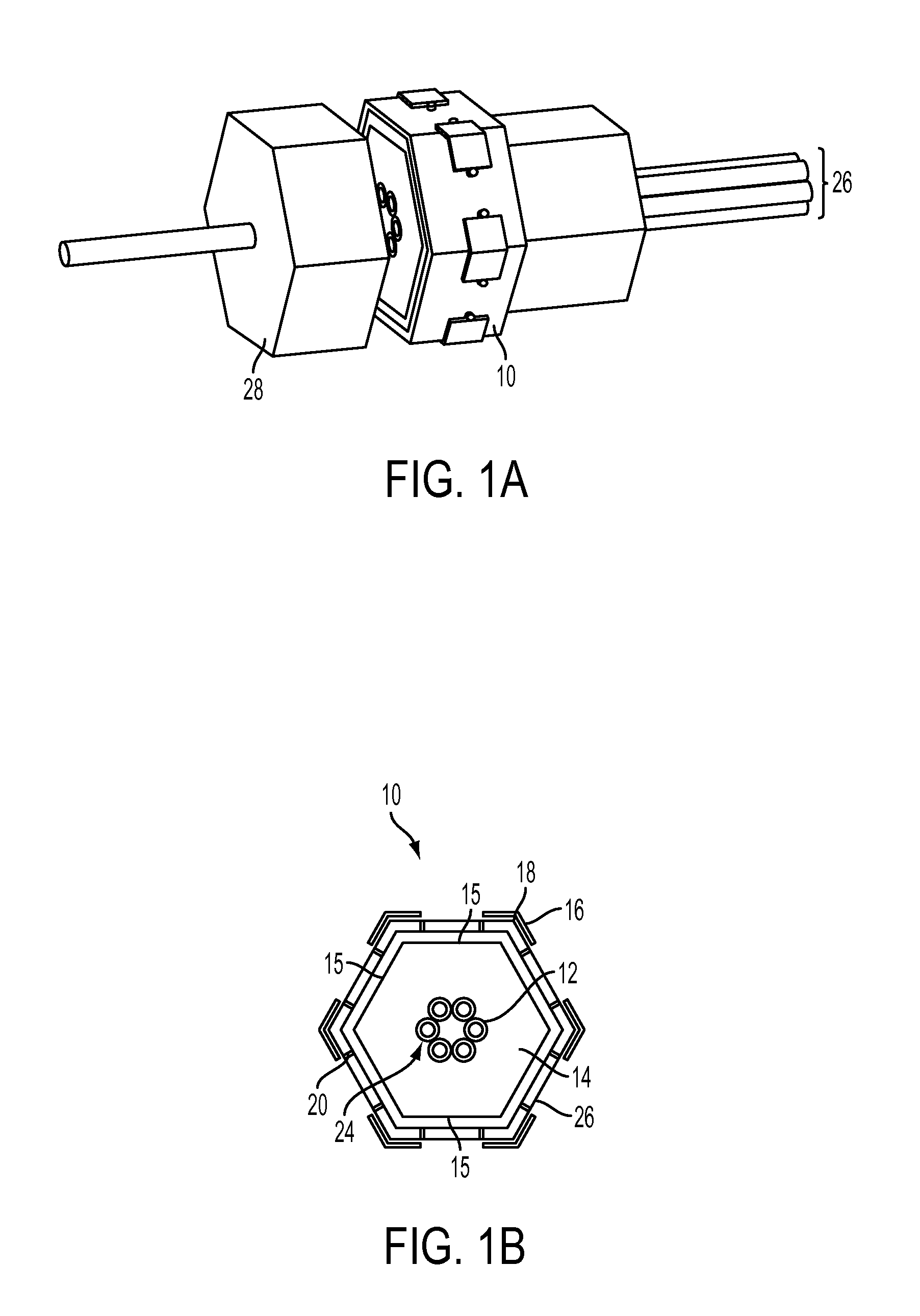
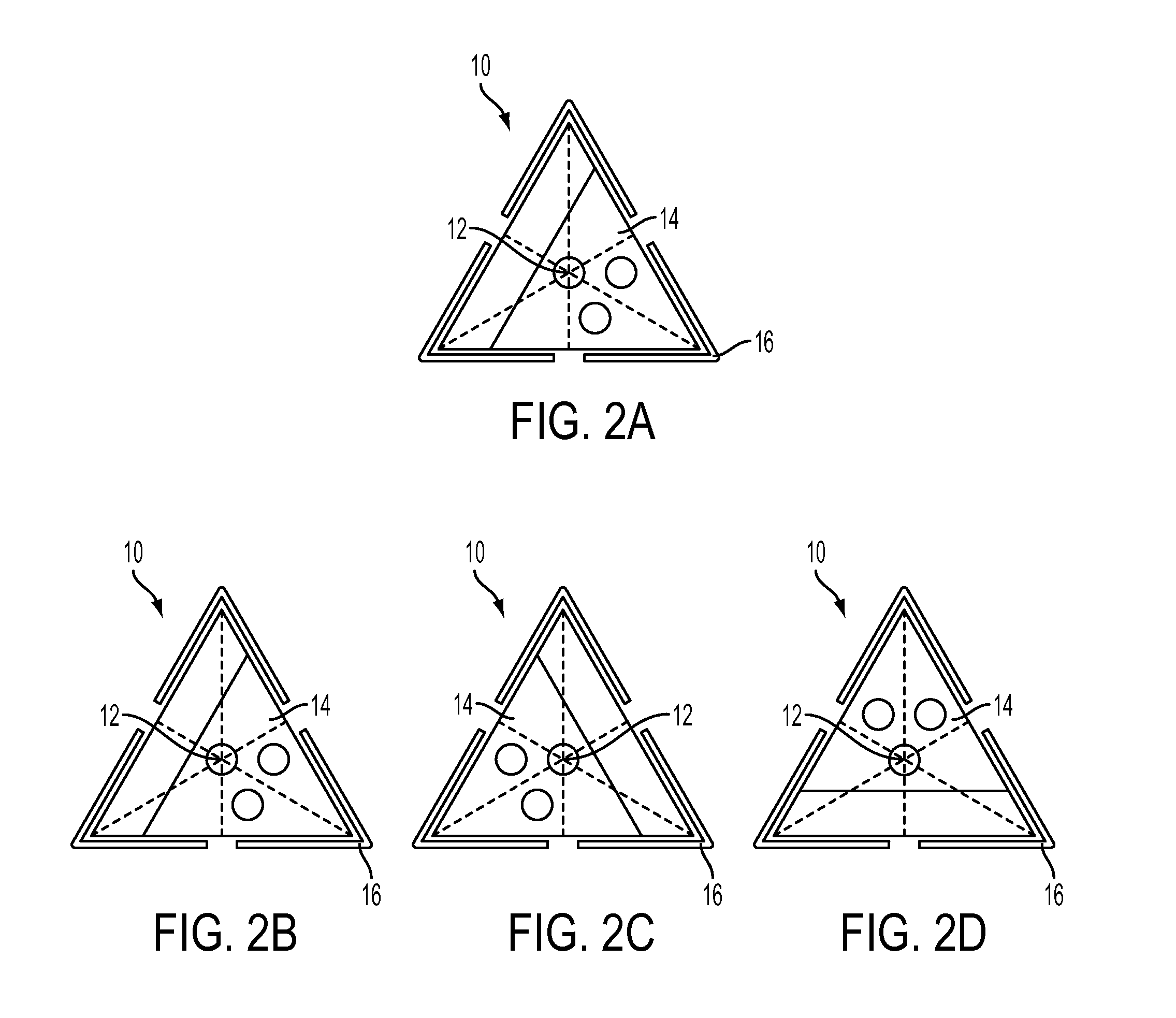
[0022]A diagram of one embodiment of the N port fiber optical switch 10 (with “N” indicating a variable, vs. fixed, number of ports, the number of ports being determined by the application / system requirements in which switch 10 is used, as is further discussed below) is shown in FIGS. 1A-B. Switch 10 consists of an optical fiber 12 mounted in a movable frame or housing 14 having a perimeter 15, a set of actuators 16 positioned along the corners 18 (or in another embodiment along the principal axis) of the movable housing 14 and as such being evenly spaced apart, a set of fine adjusters 20 for fine control of the final positions, and a group of optical fibers 24 mounted in a geometric position whose symmetry is the same as the number of ports 26 in the system. The optical fiber can be made of a variety of materials such as silica-based, fluoride-based, germanate-based and chalcogenide-based optical fibers. There are no restrictions on the type of fiber to be used including but not li...


PUM


Abstract

An N port fiber optical switch includes a movable housing having a perimeter and N corners; a plurality N of optical fibers positioned within the housing and inside the perimeter; and a plurality N of actuators, wherein each actuator is positioned on a corresponding corner such that when selectively activated one or more of the actuators urges the movable housing and the plurality of optical fibers to a selected switch position. The switch provides short switching times and high power handling while allowing for a large number of ports and provides the capability of interfacing with and switching between a variable number of ports.

Description

CROSS-REFERENCE TO RELATED APPLICATIONS[0001]This Application claims the benefit of U.S. Provisional Application 61 / 568,706 filed on Dec. 9, 2011 and incorporated herein by reference.FIELD OF THE INVENTION[0002]The invention is directed to an optical switch, and in particular to an N port optical switch.BACKGROUND OF THE INVENTION[0003]Fiber optics switches are usually characterized with respect to their losses (insertion, transmission and reflection), switching time, repeatability, long term stability, temperature and vibration resistance, power handling, wavelength-range and number of ports. Various architectures and concepts have been proposed for optical routing with fiber optical switches among them systems based on movement (e.g. physical translation and bending) of fibers by directly moving the fiber, by moving the position of a reflective or refractive object, by altering the polarization in birefringent systems and through interferences caused by changes in the phase (spati...

Claims


Application Information

Patent Timeline
Patent Type & Authority Patents(United States)
IPC IPC(8): G02B6/26G02B6/35
CPCG02B6/35G02B6/3508G02B6/3558G02B6/3572
Inventor GATTASS, RAFAELKUNG, FREDERIC H.SHAW, LESLIE BRANDONAGGARWAL, ISHWAR D.SANGHERA, JASBINDER S.BUSSE, LYNDA E
Owner UNITED STATES OF AMERICA
Learn More