
Method and device for generating of a signal that reflects respiratory efforts in patients on ventilatory support

a technology of respiratory effort and signal, applied in the field of assisted mechanical ventilation, can solve the problems of ineffective effort, effort completely failing to trigger the ventilator, and often marked trigger delay

Active Publication Date: 2014-12-30
YRT
View PDF15 Cites 11 Cited by
  • Summary
  • Abstract
  • Description
  • Claims
  • Application Information

AI Technical Summary

Benefits of technology

The present invention provides a method for generating a signal that mirrors changes in the level of effort exerted by respiratory muscles of patients on mechanical ventilatory support. This is achieved by monitoring airway pressure, rate of gas flow, and volume of gas flow of the patient and using a combination of coefficients to convert the data into a composite pressure signal. The method allows for the identification of transients in the airway pressure and gas flow data, and the selection of points in the exhalation phase of the patient where the values of the data are stable. The method can adjust the levels of effort exerted by the patient by adjusting the values of the coefficients and can be used to improve patient-ventilator interaction. The generated signal can be displayed on a monitor or communicated to a user through other means of communication.

Problems solved by technology

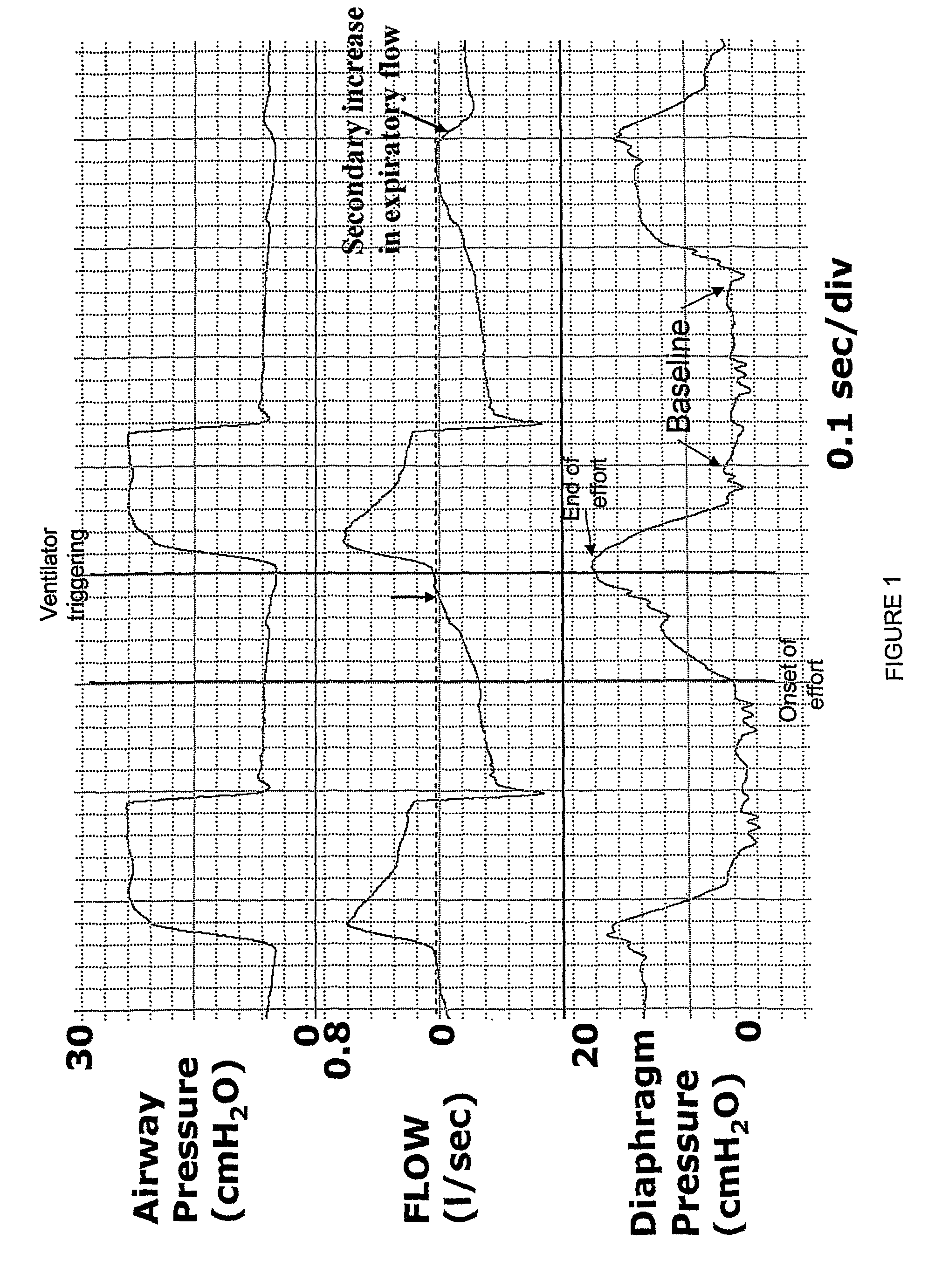
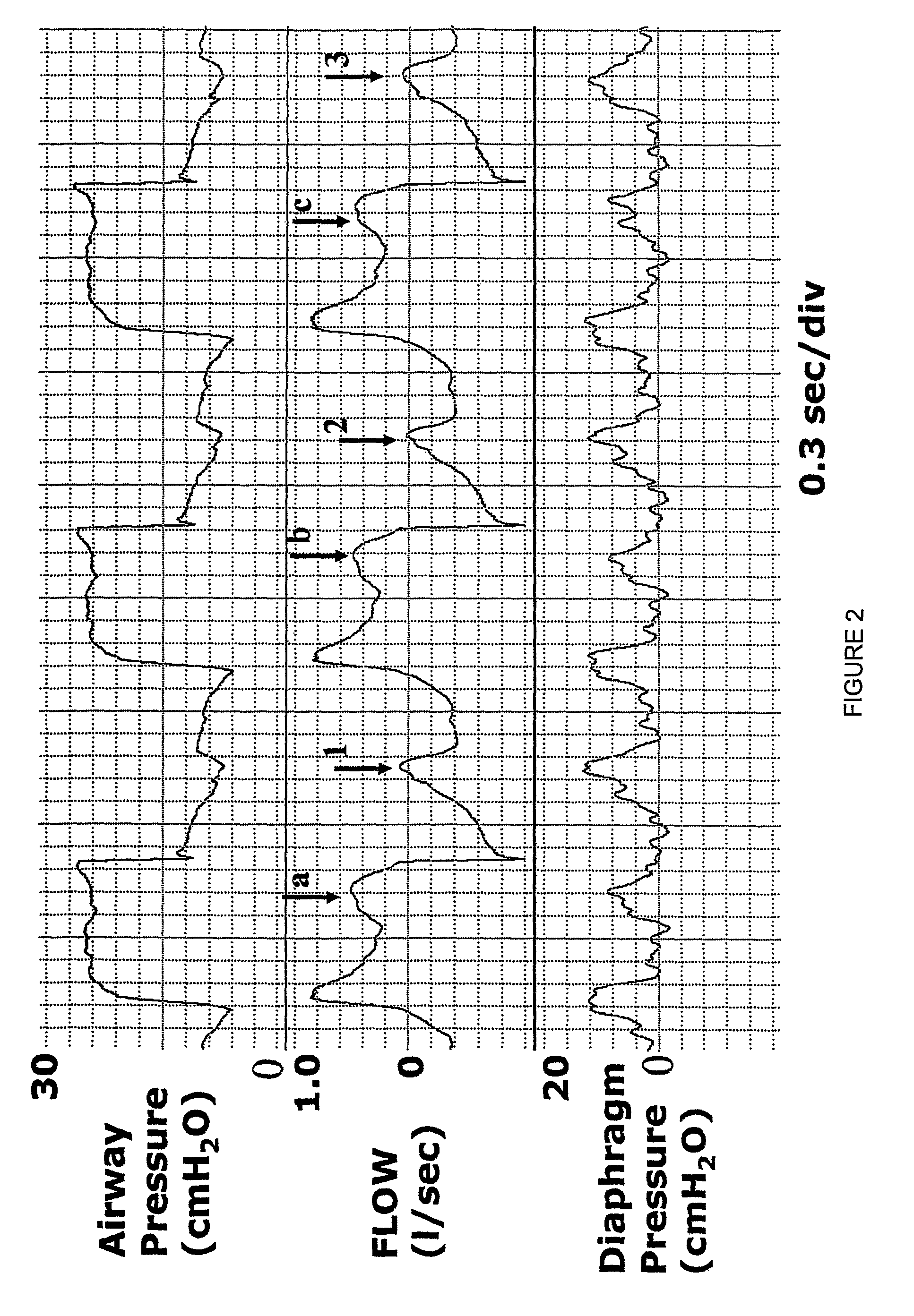
Trigger delay is often so marked that some efforts completely fail to trigger the ventilator (ineffective efforts, e.g. third effort, FIG. 1).
There are, accordingly, two inspiratory efforts within a single inflation phase and there is an additional ineffective effort during the ventilator's expiratory phase.
Non-synchrony is believed to cause distress, leading to excessive sedation and sleep disruption, as well as errors in clinical assessment of patients since the respiratory rate of the ventilator can be quite different from that of the patient.
Thus, if the response of the ventilator is poor, triggering may not occur immediately when the triggering criteria are reached.
This component of trigger delay can, however, still be excessive if the user sets an unnecessarily high threshold.
This setting may be because of lack of sufficient expertise, or because there was excessive baseline noise at some point, which necessitated a high threshold to avoid auto-triggering.
This delay is related to the fact that expiratory resistance is usually high in ventilated patients and expiratory time is frequently too short to allow lung volume to return to FRC (functional residual capacity) before the next effort begins.
Cycling-off errors result from the fact that, except with Proportional Assist Ventilation, current ventilator modes do not include any provision that links the end of ventilator cycle to end of the inspiratory effort of the patient.
Furthermore, while this method may yield reasonably accurate results in the intended application (treatment of obstructive sleep apnea patients with non-invasive BiPAP), a number of considerations suggest that its use in critically ill, intubated, ventilated patients may not provide accurate results:
Thus, changes in inspiratory flow profile cannot be used to reflect similar changes in alveolar pressure.
The use of flow to infer end of effort during the inflation phase is accordingly not plausible.
This considerably decreases the sensitivity and specificity of flow pattern as a marker of inspiratory effort.
However, a change in flow trajectory also results in changes in volume and Paw trajectories.
However, it is not possible to prospectively identify that a trajectory change took place in a timely manner, for the sake of triggering the ventilator.
There is always uncertainty with extrapolation, particularly with non-linear functions where the exact function is not known and, even more so, when the signal is noisy, as the flow signal commonly is (due to cardiac artefacts or secretions).
Otherwise, false triggering will occur frequently.
Thus, in the average mechanically ventilated patient the use of flow trajectory to identify Tonset is not likely to result in a significant improvement over the current approach of waiting for flow to become inspiratory.
Even an experienced eye, with the benefit of hindsight, cannot distinguish between a true trajectory change and some flow artefact.
In summary, the use of flow to identify respiratory phase transitions is entirely unsuitable for identification of inspiratory to expiratory transitions during mechanical ventilation in critically ill patients (because of the highly variable Paw during inflation), and has poor sensitivity and specificity for identifying expiratory to inspiratory transitions in these patients because of the frequent use of active exhalation valves, the presence of variable time constant during expiration and the often marked abnormalities in elastance and resistance.
Although the specification suggests that appropriate values for KV and KF may be selected automatically using appropriate software, the specification does not teach any approach for doing that and it is evident that such software would have to be sufficiently sophisticated to replace the complex functions executed by the eye-brain combination in humans.
Specifically, these methods employ complex algorithms to distinguish between true baseline and noise values during expiration, a task that can be readily done by the human eye, but is very difficult to translate into computer instructions.

Method used


Image

  • Method and device for generating of a signal that reflects respiratory efforts in patients on ventilatory support
  • Method and device for generating of a signal that reflects respiratory efforts in patients on ventilatory support
  • Method and device for generating of a signal that reflects respiratory efforts in patients on ventilatory support

Examples


Embodiment Construction

[0063]The Younes approach contemplates novel methods and devices for specific and timely identification of respiratory phase transitions within the patient for use in monitoring patient-ventilator interaction or to effect switching of ventilator cycles. These methods / devices represent a progression in complexity that address the problems inherent in the prior art ventilation procedures described above.

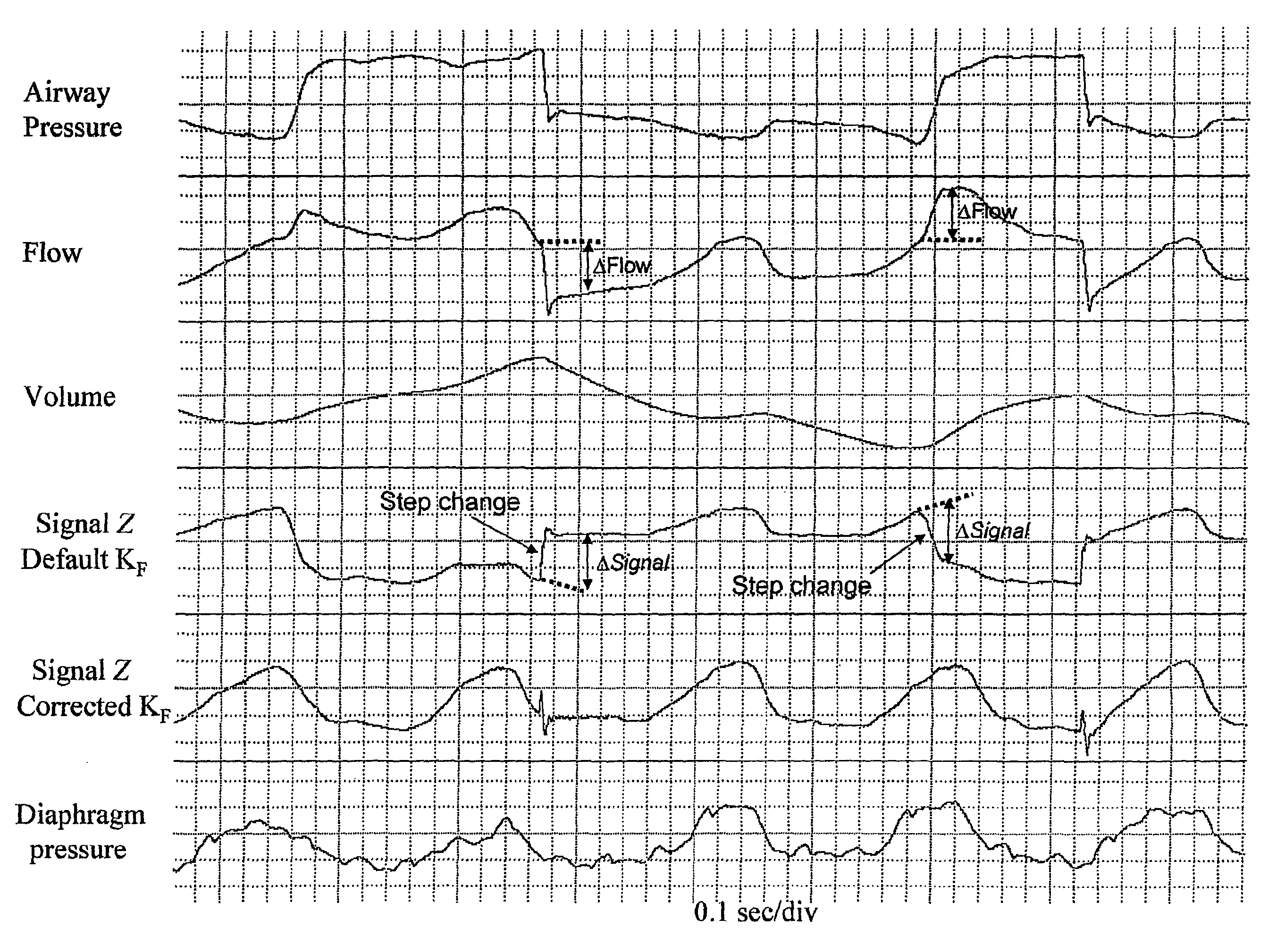
[0064]In the simplest of these methods, a Signal is generated (Signal X) that incorporates changes in both the flow and airway pressure (Paw) information. Thus,

Signal X=(Flow*Kf)−Paw  Equation 2,

[0065]where, Kf is a constant that converts flow to pressure. Kf may be an estimated or assumed value of patient's resistance (including endotracheal tube). There are two advantages to this approach over the use of flow alone: First, the Signal becomes relatively immune to changes in flow trajectory produced via changes in pressure at the exhalation / PEEP valve mechanism (#1 in Background above)...


PUM


Abstract

A method and device for generating a signal that mirrors changes in the level of effort exerted by respiratory muscles of patients on mechanical ventilatory support comprising: monitoring and storing airway pressure (Paw), rate of gas flow (F), and volume of gas flow (V), and generating a composite pressure signal using resistive pressure units (KF) determined from elapsed data and selected to minimize step changes in the calculated signal and elastic pressure units (Kv) determined from elapsed data by steps comprising: —scanning stored F or Paw during exhalation and identifying where their trajectory transiently reverses direction to detect transients; —selecting points within the exhalation that are at preselected distances away from the transients; —calculating the value of Kv required to force the values of the calculated signal at said selected points in elapsed breaths to be substantially equal when the selected value of KF is used as the flow coefficient.

Description

REFERENCE TO RELATION APPLICATIONS[0001]This application is a U.S. National Phase filing under 35 USC 371 of PCT / CA2006 / 000756 filed May 12, 2006.FIELD OF INVENTION[0002]This invention relates to assisted mechanical ventilation.BACKGROUND TO THE INVENTION[0003]Ventilatory assist devices are machines used in the treatment of respiratory failure and sleep disorders in hospital or home settings. With assisted ventilation (e.g. assist volume cycled ventilation, pressure support ventilation, bi-level assist in the case of non-invasive devices and proportional assist ventilation) ventilator cycles are triggered by the patient and are intended to coincide with patient's inspiratory effort, beginning the support when inspiratory effort starts and ending the support at the end of patient's inspiratory effort. In practice, however, the ventilator cycle never begins at the onset of patient's inspiratory effort (trigger delay) and the end of the ventilator's inflation phase only rarely coincide...

Claims


Application Information

Patent Timeline
Patent Type & Authority Patents(United States)
IPC IPC(8): A61B5/00A61B5/08A61M16/00A61B5/085
CPCA61B5/085A61B5/7239A61M2016/0039A61M16/0051A61M2016/0042A61M2016/0027A61M2230/46A61M16/026
Inventor YOUNES, MAGDY
Owner YRT
Learn More