
A system and a corresponding method for estimating respiratory drive of mechanically ventilated patients

a mechanical ventilator and patient technology, applied in the direction of mechanical apparatus, respirator, operating means/releasing devices, etc., can solve the problems of respiratory muscles weakened or tired, reduced chemoreceptor response, signaling insufficient, etc., to improve diagnosis and selection of mechanical ventilator settings, and improve patient understanding

Active Publication Date: 2016-05-05
TYCO HEALTHCARE GRP LP
View PDF8 Cites 4 Cited by
  • Summary
  • Abstract
  • Description
  • Claims
  • Application Information

AI Technical Summary

Benefits of technology

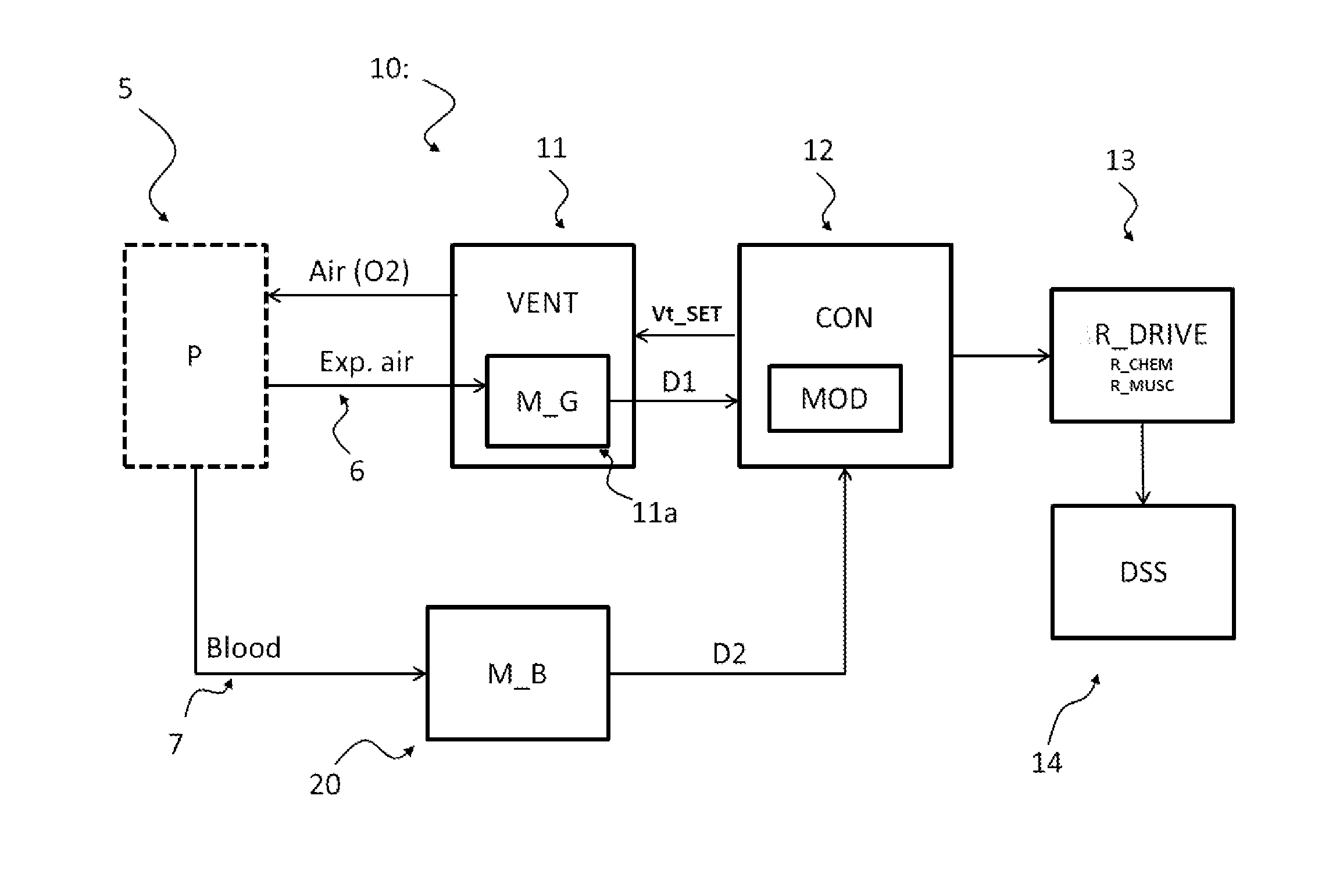
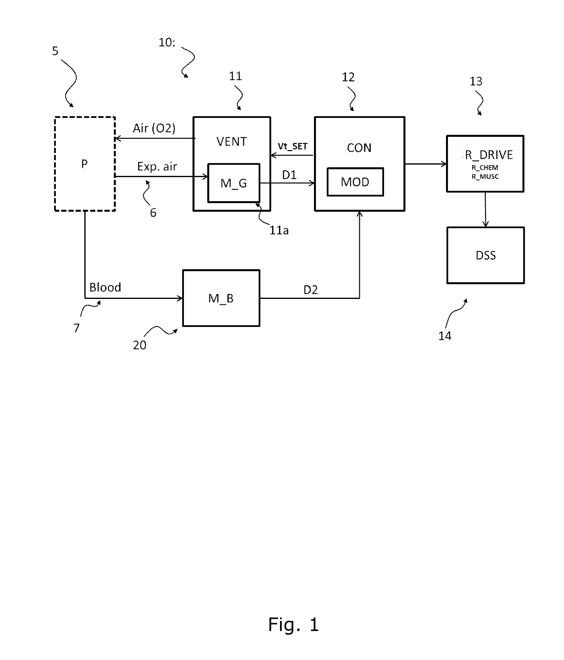
This patent describes a system and method to measure the breathing of a patient who is being ventilated mechanically. This is done by measuring changes in the patient's volume support or pressure support, and also monitoring the response of the ventilator parameters like respiratory frequency. By analyzing these changes, the system can estimate the patient's breathing drive and try to identify the components that are related to the patient's chemical and muscle response. This helps to better understand the patient's needs and to adjust the ventilator settings accordingly. Overall, this system and method can improve the diagnosis and treatment of patients who are ventilated mechanically.

Problems solved by technology

In disease, or in other situations such as the administration of opioids and other drugs, chemoreceptor response may be reduced, and signaling insufficient.
In disease, the respiratory muscles may be weakened or tired and as such unable to contract the appropriate amount.
An inherent disadvantage by this method is the need for measuring neural drive by an electrode in the diaphragm which is typically inserted into the oesophagus.

Method used


Image

  • A system and a corresponding method for estimating respiratory drive of mechanically ventilated patients
  • A system and a corresponding method for estimating respiratory drive of mechanically ventilated patients
  • A system and a corresponding method for estimating respiratory drive of mechanically ventilated patients

Examples


example

[0076]FIGS. 4 and 5 exemplify the technique using data collected from two patients (one for each figure). In FIG. 4, plots are shown of changes in tidal volume (Vt) against A) respiratory frequency, B) end tidal CO2 and C) arterial pH. The dashed curve in FIG. 4A represents the model simulated response of these variables assuming normal muscular and chemical response, normal values of metabolism, e.g. rate of tissue CO2 production, and normal values of the acid-base status of blood and CSF. Stars, solid circles, crosses, diagonal crosses, open circles and triangles on plots 4A-C represent data collected at different values of Vt, with each symbol representing a different value of ventilator setting on the ventilator, Vt_SET. It should be noted this data has been collected and plotted with volume as a variable, but in clinical practise the pressure is often applied as the variable instead. This is however equivalent as the skilled person will understand, and does not change the overa...

embodiment 1

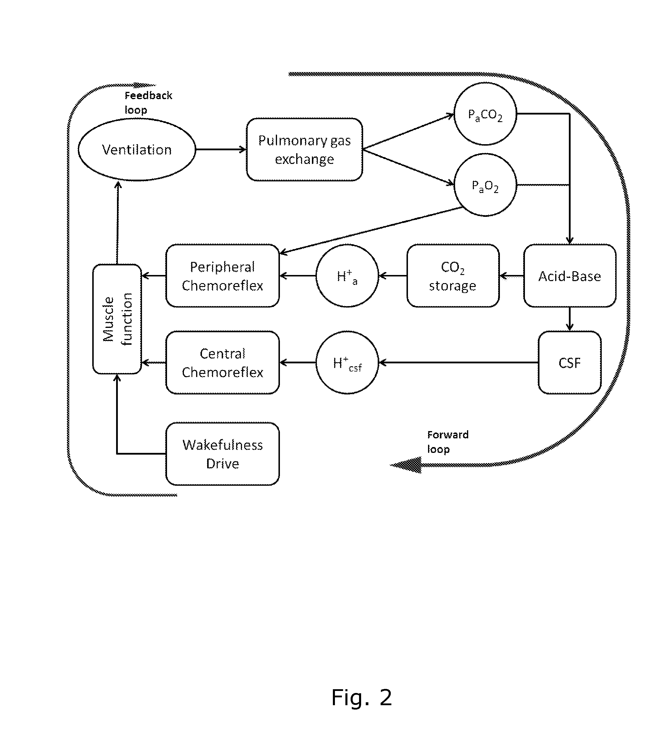
2. The mechanical ventilation system , wherein the physiological model (MOD) comprises a component of the total respiratory drive being indicative of muscular response (R_MUSC).

3. The mechanical ventilation system according to embodiment 1 or 2, wherein the physiological model (MOD) comprises a component of the total respiratory drive being indicative of chemical response (R_CHEM), preferably a subcomponent indicative of the central chemical response and a subcomponent indicative of the peripheral chemical response.

4. The mechanical ventilation system according to any of embodiments 1-3, wherein the control means is arranged for estimating both the muscular response (R_MUS) and chemical response (R_CHEM) forming part of the total respiratory drive (R_DRIVE).

5. The mechanical ventilation system according to any of embodiments 1-4, wherein the control means is arranged for estimating the muscular response (R_MUS) and chemical response (R_CHEM) by initially assuming one of the two resp...


PUM


Abstract

The present invention relates to a system (10) and a corresponding method for estimating the respiratory drive (R_DRIVE) of mechanically ventilated patients, and for preferably apportioning this respiratory drive into one, or more, components related to the chemical drive—i.e. the drive due to the chemoreceptor response—and / or the muscular drive—i.e. the contraction of respiratory muscles, for example the diaphragm. The principle of the invention is that respiratory drive can be obtained from measuring the patient's response to small changes in mechanical ventilation settings (Vt_SET), and that this can be apportioned into chemical and / or muscular effects depending upon the changes in respiratory frequency, and / or arterial or end tidal CO2 levels, and / or arterial blood p H.

Description

TECHNICAL FIELD OF THE INVENTION[0001]The present invention relates to a system and a corresponding method for estimating the respiratory drive of mechanically ventilated patients. More particularly, for apportioning this respiratory drive into one, or more, components related to chemical drive—i.e. the drive due to the chemoreceptor response—and / or muscular drive—i.e. the contraction of respiratory muscles, for example the diaphragm.BACKGROUND OF THE INVENTION[0002]Patients residing at the intensive care unit typically receive mechanical support for their ventilation. Selecting the appropriate level of mechanical ventilation is not trivial, and it has been shown that appropriate settings can reduce mortality [1].[0003]Notice that a device or system capable of performing mechanical ventilation is sometimes called an artificial breathing machine, a life support device, or, more popularly, a respirator.[0004]Typically, patients are ventilated using “support” modes. In these modes, pat...

Claims


Application Information

Patent Timeline
IPC IPC(8): A61M16/00
CPCA61M16/0069A61M16/0003A61M2016/0027A61M2230/205A61M2230/202A61M2230/432A61M2230/208A61M2205/3334A61M16/12A61M2016/0039A61M2016/0042A61M2202/0464A61M2230/42A61M2230/435A61M16/026
Inventor REES, STEPHEN EDWARDKARBING, DAN STIEPERRICO, SEBASTIAN LARRAZA
Owner TYCO HEALTHCARE GRP LP
Learn More