Method and device for coating substrates from the vapor phase

a technology of substrates and vapor phases, applied in vacuum evaporation coatings, chemical vapor deposition coatings, coatings, etc., can solve the problems of low yield of vaporization materials, low yield due to separation between vaporizer sources and substrates, and use of electron beam guns, so as to maximize the yield of materials deposited, the effect of minimizing heat input on the substra

Inactive Publication Date: 2014-12-16
VON ARDENNE ANLAGENTECHNIK GMBH
View PDF39 Cites 0 Cited by
  • Summary
  • Abstract
  • Description
  • Claims
  • Application Information

AI Technical Summary

Benefits of technology

[0048]In another embodiment of the invention, the heating apparatus is configured as a flashlamp, for example as a xenon flashlamp. The heat input onto the substrate can thereby be minimized, so that even particularly temperature-sensitive substrates can be coated.
[0049]In another embodiment of the invention, a further vaporization device for vaporizing a second vaporization material is arranged between the vaporization device in the first position and the substrate in the second position. This is advantageous in particular when co-vaporization of two or more materials is intended to be carried out with the device according to the invention.
[0050]In another embodiment of the invention, heated vapor shutters are arranged in the region of the vapor tubes of the first and second vaporization devices. These are advantageous in particular for maximizing the yields of the materials deposited.

Problems solved by technology

Disadvantages with this, however, are primarily the low yield of the vaporization material, which often ranges only in the region of a few percent.
This is unacceptable particularly for the case of organic materials, which constitute the main cost factor in the production of OLEDs and organic solar cells.
Disadvantages with this device and the associated method are, again, the low yields due to the separation between the vaporizer source and the substrate, particularly when a plurality of materials are vaporized simultaneously.
The disadvantage with this arrangement consists primarily in the use of the electron beam gun, which is unsuitable for use when vaporizing organic materials.
Furthermore, it is not possible to coat flat substrates with the device disclosed in U.S. Pat. No. 4,748,313 A.
A disadvantage in this case is, in particular, the elaborate production of the pellet from the organic materials.
The disadvantage with this device resides primarily in the fact that the device proposed in US 2005 / 0281050 A1 and the associated method are unsuitable for ensuring continuous coating with the required throughput rates.
The disadvantage with using strip-shaped intermediate carriers resides primarily in the materials that can be used for the required flexibility, which leads to a great restriction in terms of the organic materials to be deposited.
However, it has been found that endless bands made of steel cannot be produced in a form suitable for use as intermediate carriers.
This is primarily because chemically inert steel bands, which are not meant to enter into a reaction with any of the organic materials deposited, are too brittle and therefore appear unsuitable for production as a steel band.
Furthermore, it has been found that circular disk-shaped intermediate carriers for use in continuous coating systems with a diameter of more than 1 m cannot be produced with the required accuracy, or if so only with high outlay.

Method used


Image

  • Method and device for coating substrates from the vapor phase
  • Method and device for coating substrates from the vapor phase

Examples


Embodiment Construction

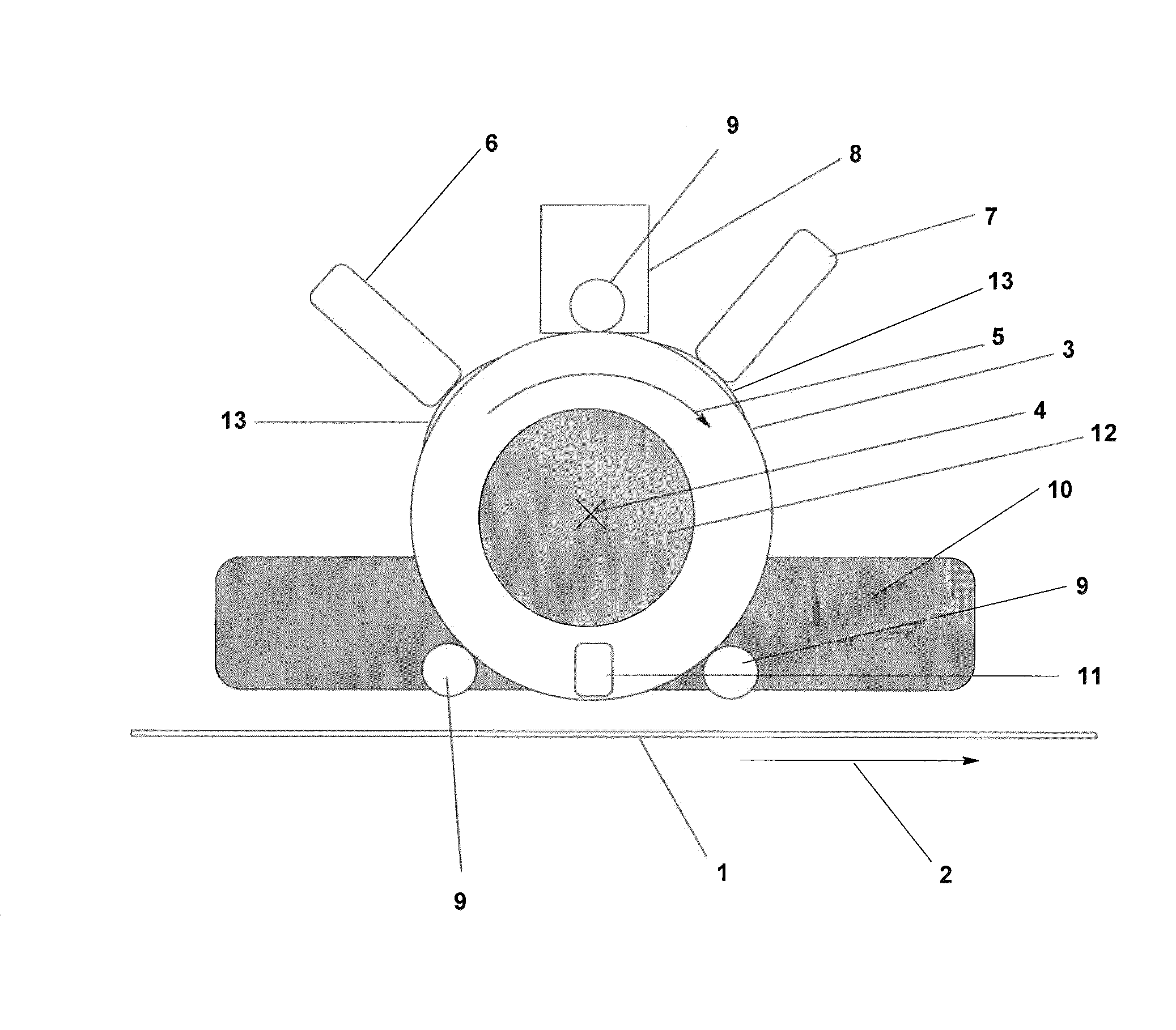
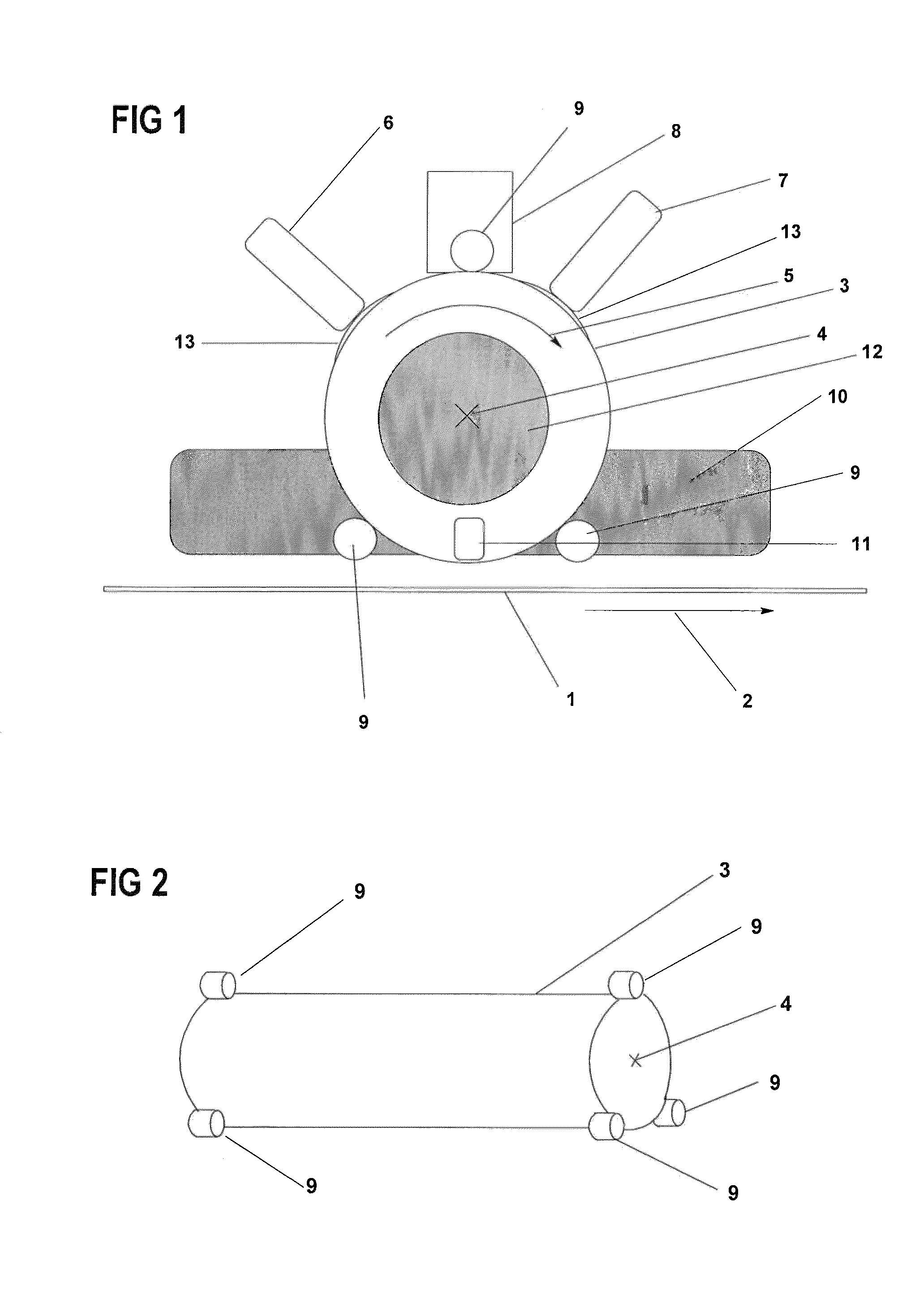
[0054]In a continuous coating system in FIG. 1, a cylindrical intermediate carrier 3 is used for coating the substrate 1, which is transported continuously in a substrate transport direction 2, with vaporization material. The cylindrical intermediate carrier 3 may, for example, consist of a quartz drum which is coated with an absorber layer consisting of CrN / SiO2, the SiO2 layer being intended to prevent possible oxidation of the CrN layer. The external diameter of the quartz drum in the present exemplary embodiment is 300 mm. The wall thickness of the quartz drum is 10 mm. The cylindrical intermediate carrier 3 rotates with a constant speed about the rotation axis 4 and in the rotation direction 5.

[0055]The coating of the intermediate carrier 3 with a first vaporization material is carried out by means of a vapor tube 6 of the first vaporization apparatus in a first position. The vapor tube may, for example, consist of SiC and comprise a line source with a rectangular box fixture. ...


PUM

PropertyMeasurementUnit
distanceaaaaaaaaaa
distanceaaaaaaaaaa
diameteraaaaaaaaaa

Abstract

In a method for coating substrates with materials to be vaporized in a vacuum coating system, the vaporization material is deposited on the substrate by double vaporization using an intermediate carrier. The intermediate carrier is continuously moved and cylindrical.

Description

CROSS REFERENCE TO RELATED APPLICATIONS[0001]This application is a national stage filing under section 371 of International Application No. PCT / EP2010 / 063031 filed on Sept. 6, 2010, and published in German on Mar. 10, 2011 as WO 2011 / 026971 and claims priority of German application No. 10 2009 040 086.9 filed on Sept. 4, 2009, the entire disclosure of these applications being hereby incorporated herein by reference.BACKGROUND ART[0002]The invention relates to a method for coating substrates with materials to be vaporized in a vacuum coating system, wherein the material to be vaporized is heated in a vaporization device, vaporized and deposited on a substrate. The vaporization material is deposited on the substrate by double vaporization using an intermediate carrier, and the intermediate carrier is moved continuously.[0003]The invention furthermore relates to a device for coating substrates with materials to be vaporized, comprising a vaporization device for vaporizing the materials...

Claims


Application Information

Patent Timeline
Patent Type & Authority Patents(United States)
IPC IPC(8): C23C14/12C23C14/24C23C16/00C23C14/54
CPCC23C14/24C23C14/12C23C14/541
Inventor GROSS, HARALD
Owner VON ARDENNE ANLAGENTECHNIK GMBH
Why Eureka
Try Eureka