
Transmitter

a transmitter and receiver technology, applied in the field of transmitters, can solve the problems of undesirable noise, high frequency harmonics generated in addition to the signal at the desired frequency, and interference with the signals received by the mobile telephone receiver, so as to reduce the current output, reduce the current, and limit the distortion of the transmitted signal

Active Publication Date: 2014-12-09
QUALCOMM TECH INT
View PDF5 Cites 0 Cited by
  • Summary
  • Abstract
  • Description
  • Claims
  • Application Information

AI Technical Summary

Benefits of technology

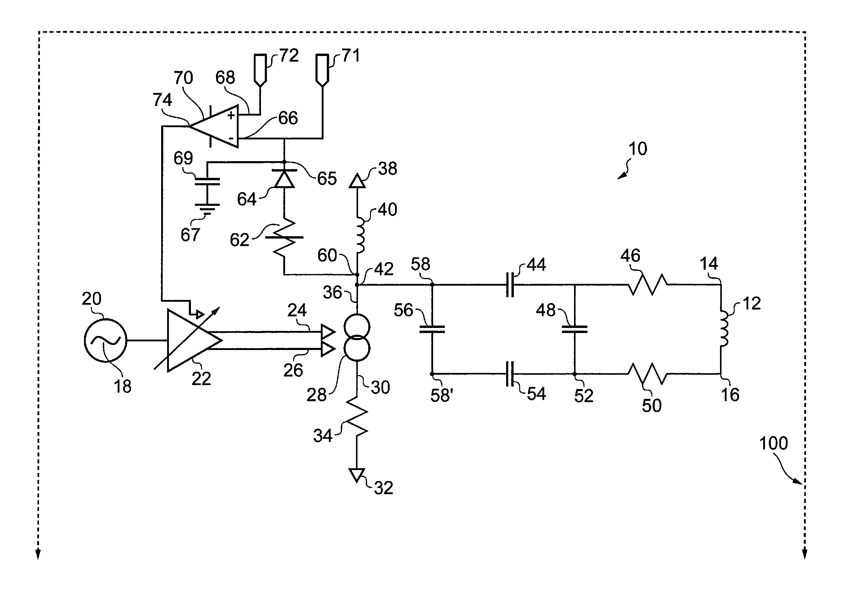
[0009]According to a first aspect of the present invention a transmitter for transmitting signals in a near-field communication (NFC) frequency band comprises an antenna; a first current source for generating a first current to excite the antenna; a first detector for detecting a first voltage at an output of the first current source; and means for reducing the current output by the first current source if the detected first voltage exceeds a first predefined threshold. An advantage of the transmitter including means for reducing the current is that distortion in the transmitted signal can be limited, and the risk of components in the transmitter being damaged can be reduced.

Problems solved by technology

Therefore, if such a known NFC transmitter is installed in a mobile telephone, the higher frequency harmonics generated in addition to the signal at the desired frequency are likely to interfere with signals received by the mobile telephone receiver.
If the mobile telephone is also installed with an NFC receiver, then signals transmitted by the mobile telephone, which are of the same or similar frequency as those received by the NFC receiver, are likely to interfere with received NFC signals.
Interference between the NFC signals and the mobile telephone signals can cause undesirable noise, for example during a telephone conversation.
Similarly, if the mobile telephone signal interferes with the NFC receiver (that is the NFC target), then the NFC initiator may not be unable to detect a response from an NFC target.
Therefore, mobile telephone devices that have NFC transmitters and FM receivers built in might suffer interference problems when transmitted NFC signals interfere with received FM signals.

Method used


Image

  • Transmitter
  • Transmitter
  • Transmitter

Examples


Embodiment Construction

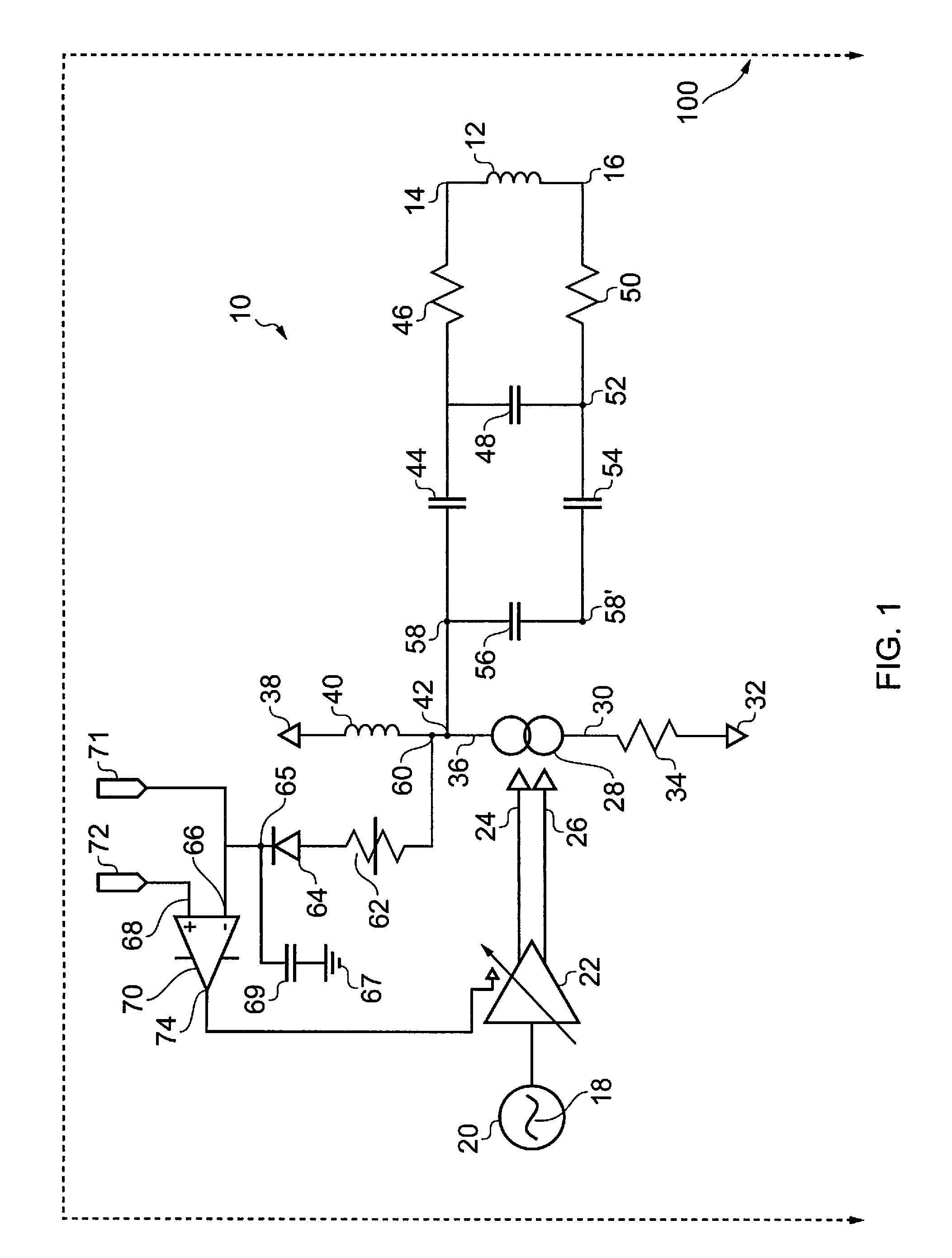
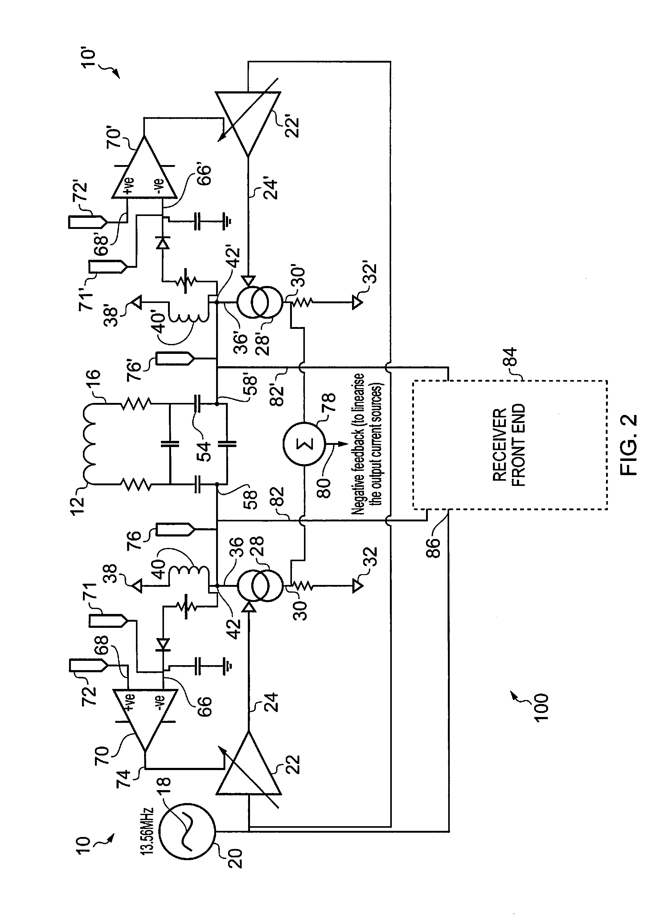
[0015]Referring to the drawings, FIG. 1 shows a circuit 10 which forms a near field communication (NFC) driver. The circuit 10 forms part of a larger circuit, shown by dashed line 100, and which will be discussed with reference to FIG. 2. The circuit 10 includes an antenna 12 which is formed of a plurality of coil turns. In the drawings of this specification, the antenna 12 is shown to have four turns. However, one skilled in the field of antenna design would appreciate that the antenna 12 may be formed of a coil having any number of turns.

[0016]The antenna 12 has a first end 14 and a second end 16. The ends 14, 16 of the antenna 12 are connected to circuitry which will be discussed in greater detail below.

[0017]A device in which the circuit 10 is installed is capable of operating in a transmit mode and in a receive mode. In the receive mode, the antenna 12 receives a signal in an NFC frequency band, and the signal is demodulated by demodulation means (not shown) via circuitry (not ...


PUM


Abstract

Systems and methods providing a transmitter for transmitting signals in a near-field communication (NFC) frequency band are disclosed. According to embodiments, a transmitter for transmitting signals in a near-field communication frequency band comprises an antenna, a first current source for generating a first current to excite the antenna, a first detector for detecting a first voltage at an output of the first current source, and means for reducing the current output by the first current source if the detected first voltage exceeds a first predefined threshold. An integrated circuit of embodiments may comprise the foregoing transmitter. A transmitter configuration of embodiments, including means for reducing the current, provides for limited distortion in the transmitted signal and reducing the risk of components in the transmitter being damaged.

Description

TECHNICAL FIELD[0001]This invention relates to a transmitter and, in particular, to a transmitter suitable for transmitting signals in a near-field communication (NFC) frequency band.BACKGROUND OF THE INVENTION[0002]Mobile communication devices, such as mobile telephones, smart phones, personal digital assistants (PDA) and laptop computers are often provided with means for communicating wirelessly with other such devices, and with other communication devices.[0003]One such means of communicating wirelessly uses near field communication (NFC). Near field communication is the name given to the communication of data over a distance of less than around 5 cm. NFC operates at a frequency of 13.56 MHz, and allows data to be transferred at rates from 106 kbit / s to 848 kbit / s. Data is transmitted between an NFC initiator and an NFC target. The initiator (often referred to as a reader) is a powered device that emits a radio frequency (RF) field. The target need not be powered, and typically t...

Claims


Application Information

Patent Timeline
Patent Type & Authority Patents(United States)
IPC IPC(8): H04B7/00
CPCG06K7/10217H04B5/0075H04B5/0056
Inventor JONES, STEVE
Owner QUALCOMM TECH INT
Learn More