
Traveling wave amplifier with suppressed jitter

a technology of traveling wave amplifier and suppressed jitter, which is applied in the direction of amplifiers with transit-time effect, differential amplifiers, amplifiers with semiconductor devices/discharge tubes, etc., can solve the problem of bringing a substantial jitter in an outpu

Active Publication Date: 2014-12-09
SUMITOMO ELECTRIC IND LTD
View PDF8 Cites 4 Cited by
  • Summary
  • Abstract
  • Description
  • Claims
  • Application Information

AI Technical Summary

Benefits of technology

The patent text describes two types of amplifiers: a traveling wave amplifier (TWA) and a driver for an electro-absorption (EA) modulator. These amplifiers have a unique design with a differential circuit that includes a pair of switching transistors and a pair of cascade transistors. Each amplifier receives an input signal with a specific delay and outputs an output signal with a different delay. The amplifiers have current providers that provide idle currents to the cascade transistors when they turn off. The technical effect of the patent text is to provide amplifiers with improved performance and efficiency for transmitting signals over optical and electrical networks.

Problems solved by technology

However, the cascade connection sometimes brings a substantial jitter in an output thereof.

Method used


Image

  • Traveling wave amplifier with suppressed jitter
  • Traveling wave amplifier with suppressed jitter
  • Traveling wave amplifier with suppressed jitter

Examples


Embodiment Construction

[0020]Next, some preferred embodiments according to the present invention will be described as referring to drawings. In the description of the drawings, numerals or symbols same or similar to each other will refer to elements same or similar to each other without overlapping explanations.

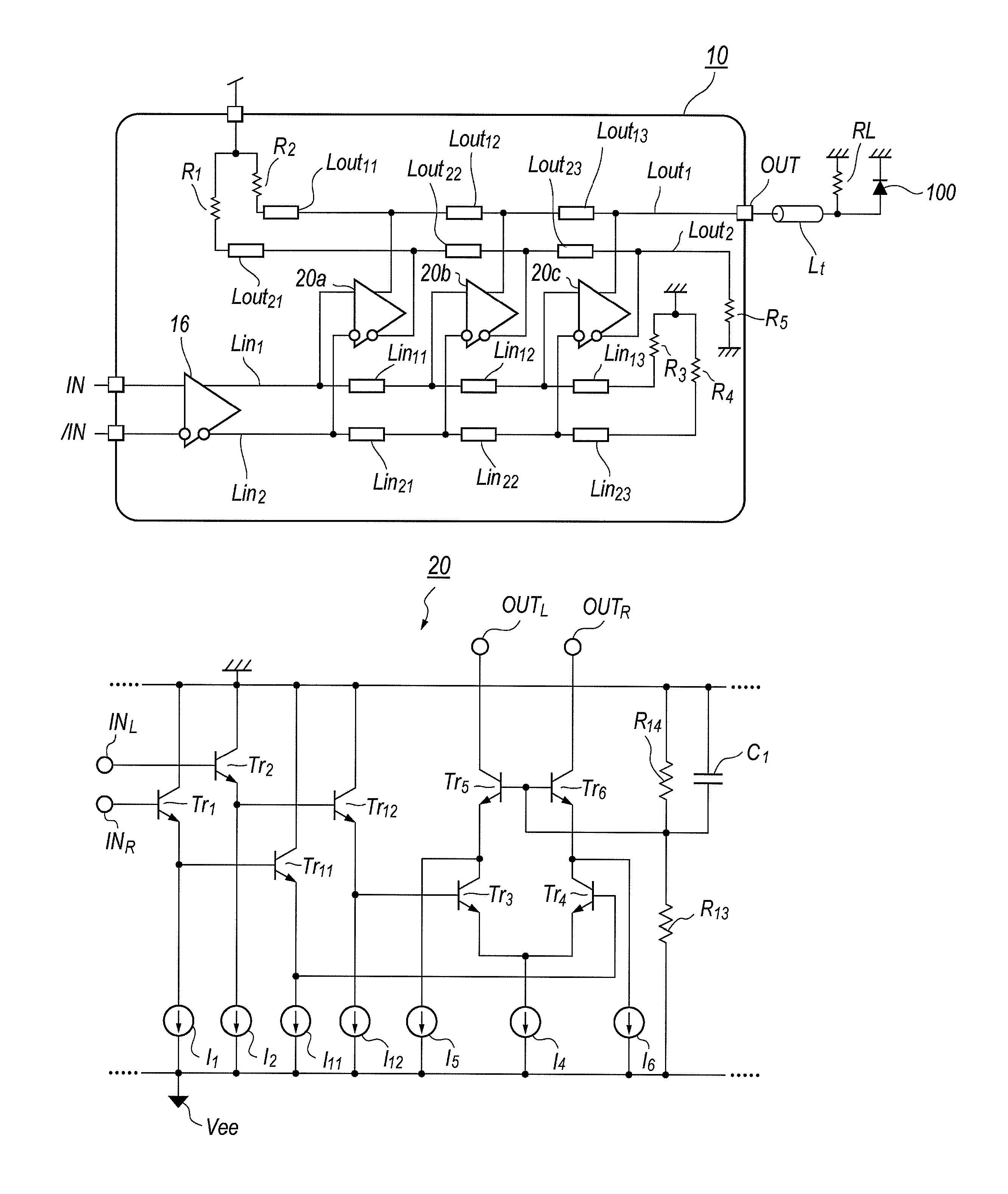
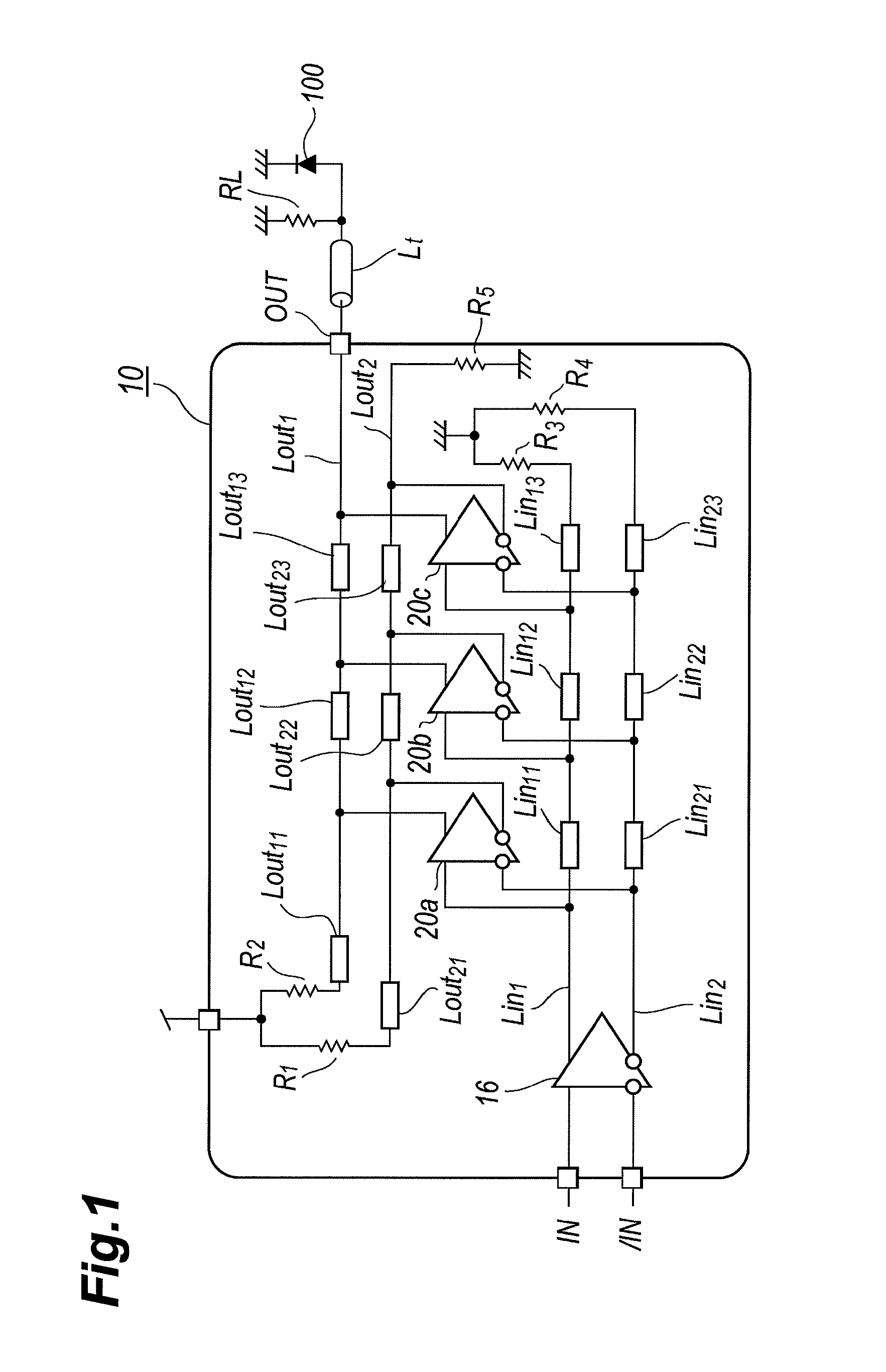
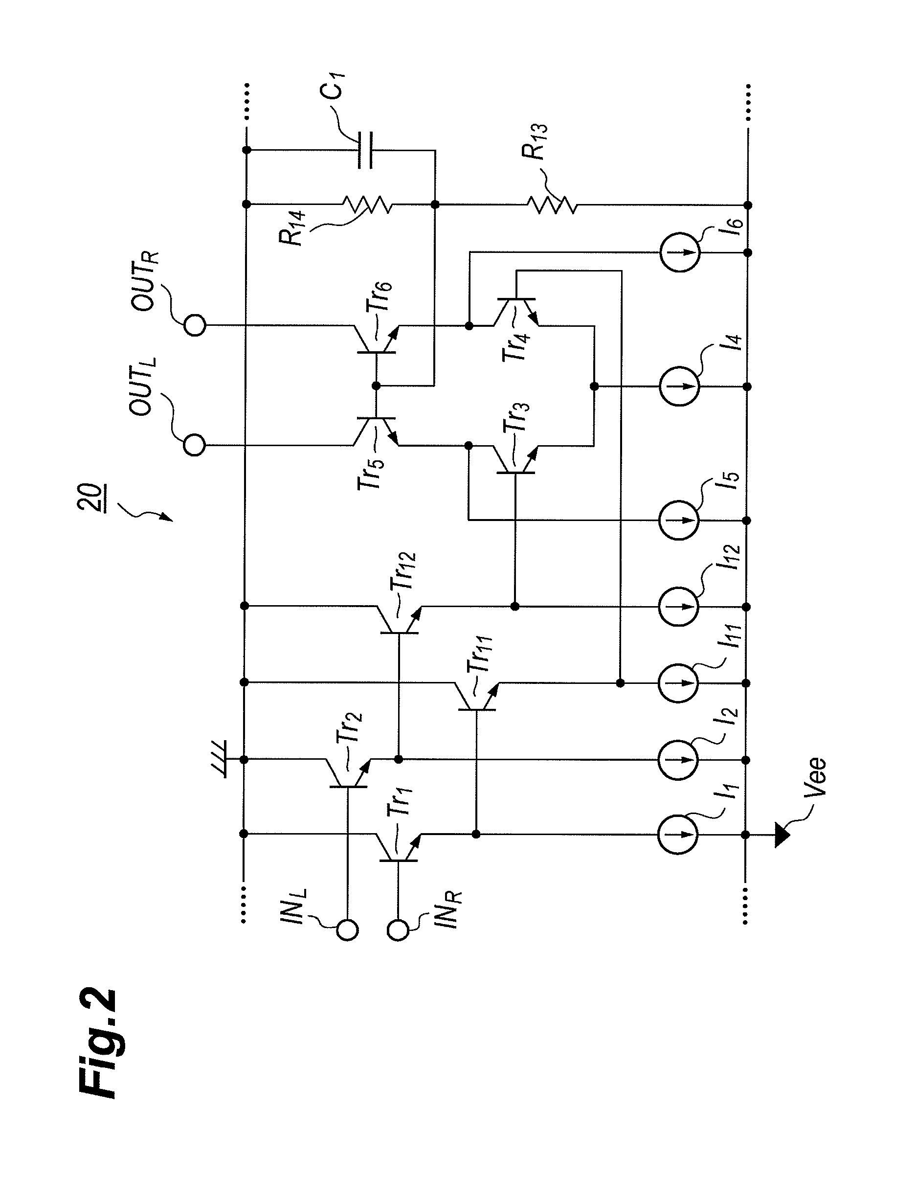
[0021]FIG. 1 is a circuit diagram of a TWA 10 according to an embodiment of the invention, and FIG. 2 shows a circuit diagram of a differential circuit 20 implemented with the TWA 10 as respective unit amplifiers, 12a to 12c. The TWA 10 of the embodiment is usable for driving optical modulator types of, for instance, the electro-absorption (hereafter denoted as EA). The EA modulator 100 shown in FIG. 1 is connected in parallel to a terminator RL, namely, a parallel circuit of the EA 100 and the terminator RL is coupled with the TWA 10 in the output thereof OUT through a transmission line Lt.

[0022]The TWA 10 includes a plurality of unit amplifiers, 12a to 12c, input transmission lines, Lin1 and Lin2...


PUM


Abstract

A traveling wave amplifier (TWA) with suppressed jitter is disclosed. The TWA includes a plurality of unit amplifiers with the differential arrangement comprised of a pair of transistors and a cascade transistors connected in series to the switching transistors. The unit amplifiers further includes current sources to provide idle currents to the cascade transistors. Even when the switching transistors fully turn off, the idle currents are provided to the cascade transistors, which set the operating point of the cascade transistor in a region where an increase of the base-emitter resistance is suppressed.

Description

BACKGROUND OF THE INVENTION[0001]1. Field of the Invention[0002]The present invention in an aspect thereof relates to a travelling wave amplifier (TWA), in particular, relates to a TWA with suppressed jitter.[0003]2. Related Background Art[0004]One type of optical transmitter often implements with an optical signal source including, for instance, a semiconductor laser diode (LD), an optical modulator type of the electro-absorption (EA) modulator or the Mach-Zhender (MZ) modulator, and a driver to drive the optical modulator. An optical transmitter whose operation speed reaches 25 Gbps, 40 Gbps and so on, sometimes exceeds these speed, is necessary for rising and falling times of an optical output therefrom less than 10 picoseconds (ps). A driver to drive such an optical modulator is inevitably requested for a wide frequency band. An amplifier, or a driver with the configuration of, what is called, the travelling wave amplifier (TWA) is one of the best solutions for the wide band amp...

Claims


Application Information

Patent Timeline
Patent Type & Authority Patents(United States)
IPC IPC(8): H03F3/68
CPCH03F2203/45612H03F2203/45374H03F3/605H03F2203/45331H03F2203/45396H03F3/45076H03F3/45085H03F3/45475
Inventor TATSUMI, TAIZOTANAKA, KEIJISAWADA, SOSAKU
Owner SUMITOMO ELECTRIC IND LTD
Learn More