
Resonator element having a mass portion

a resonator element and mass portion technology, applied in the direction of oscillator, piezoelectric/electrostrictive/magnetostrictive device, piezoelectric/electrostrictive/magnetostriction machine, etc., can solve the problem of difficult frequency adjustment, difficult to add a weight on the side surfaces of a thin vibrating arm to perform frequency adjustment of a resonator element, and difficult to perform laser light to remove a part of th

Inactive Publication Date: 2014-12-09
SEIKO EPSON CORP
View PDF43 Cites 1 Cited by
  • Summary
  • Abstract
  • Description
  • Claims
  • Application Information

AI Technical Summary

Benefits of technology

[0020]Thus, it is possible to secure an excitation electrode for exciting the vibrating arm of the resonator element so as to have a length of ½ of the entire length of the vibrating arm. Thus, it is possible to obtain sufficient vibration properties with a low CI value for practical oscillation.
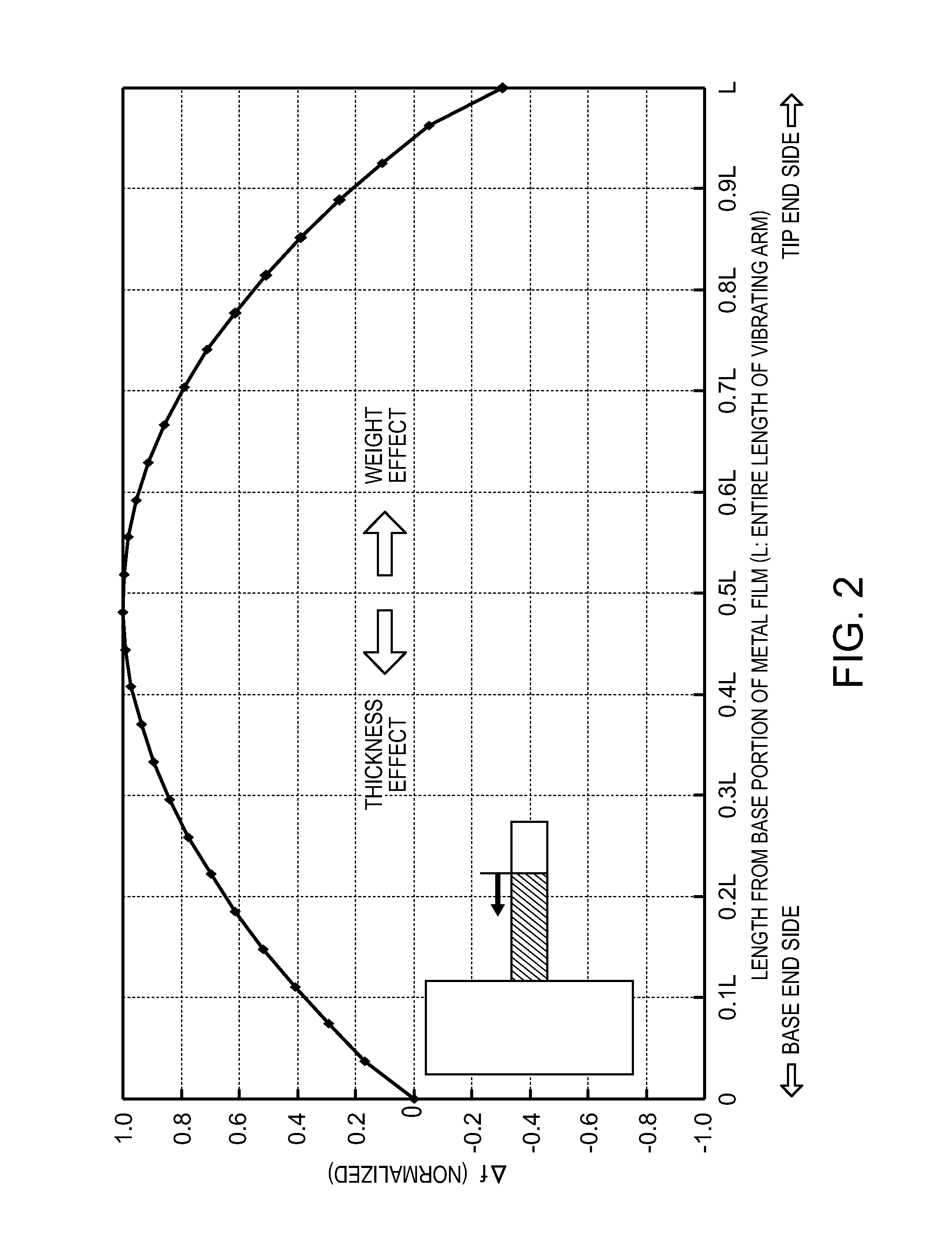
[0026]According to this configuration, by providing a material whose density D (in units of 103 kg / m3) is in the range of D>8.92 on the tip end of the vibrating arm, the tip end can be used as a portion in which rough tuning of the frequency adjustment is performed. Thus, by forming a film on the tip end of the vibrating arm, it is possible to shorten the processing time of the frequency adjustment in a resonator element in which the amount of adjustment is large and whose variation of the frequencies with the removal or addition of a film is large.Application Example 4
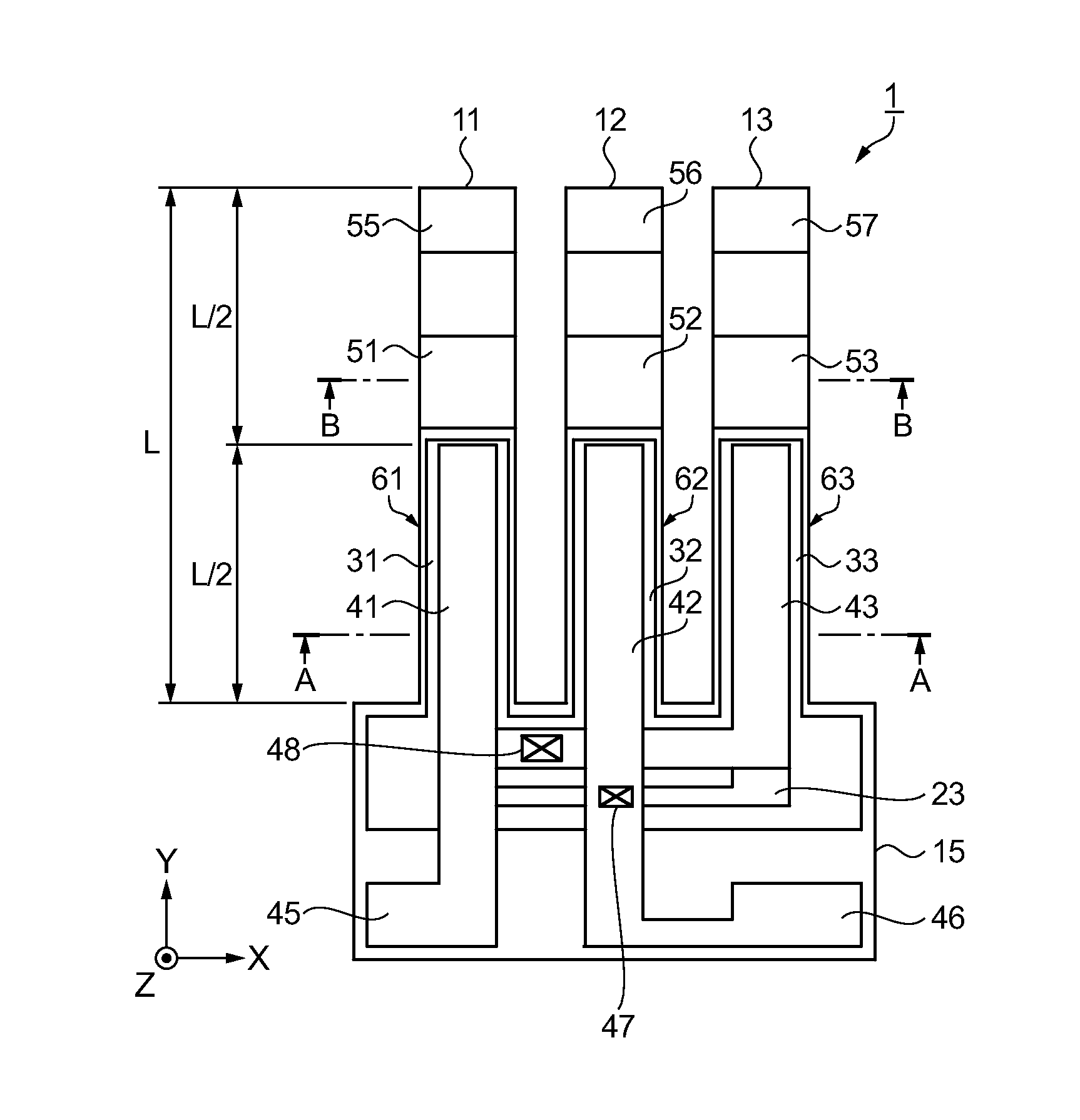
[0038]According to this configuration, the tip end of the vibrating arm is used as the second mass portion for rough tuning which is made from a material whose density D (in units of 103 kg / m3) is in the range of D>8.92, and the central portion of the vibrating arm is used as the first mass portion for fine tuning which is made from a material whose density D (in units of 103 kg / m3) is in the range of 2.20≦D≦8.92. Therefore, it is possible to form the excitation electrode so as to extend from the base-side end to the position near the center (½ L) of the vibrating arm. Accordingly, it is possible to prevent deterioration of the CI value.
[0039]Moreover, by finely tuning the frequency after the rough tuning is performed, the frequency adjustment of the resonator element can be performed effectively in a short period of time.

Problems solved by technology

However, it is difficult to add a weight on side surfaces of a thin vibrating arm to perform frequency adjustment of a resonator element.
Moreover, even when the weight can be added to the side surfaces of the vibrating arm, it is very difficult to irradiate the side surfaces with laser light to remove a part of the weight.
For this reason, it was considered difficult to perform the frequency adjustment by adding or removing a film in the thickness direction of the vibrating arm in a resonator that vibrates in the out-of-plane mode.
Thus, it is difficult to obtain favorable vibration properties in the resonator element.
For this reason, when a mass portion is provided closer to the tip end side than the half-length portion of the resonator element, a variation of the frequencies increases with the removal of the metal film or the insulating film, and fine tuning thereof is difficult.
Thus, there is a problem in that it is not possible to adjust the frequencies with high accuracy.
However, in this case, since the metal film or the insulating film is removed, for example, by irradiating it with laser light, the mass portion may cause damage to the excitation electrode on the rear surface.
Moreover, if the excitation electrode is damaged, the vibration properties of the resonator element deteriorate.

Method used


Image

  • Resonator element having a mass portion
  • Resonator element having a mass portion
  • Resonator element having a mass portion

Examples


first embodiment

[0068]FIGS. 4A to 4C show a configuration of a resonator element according to a first embodiment, in which FIG. 4A is a schematic top view, FIG. 4B is a schematic sectional view taken along the line A-A in FIG. 4A, and FIG. 4C is a schematic sectional view taken along the line B-B in FIG. 4A.

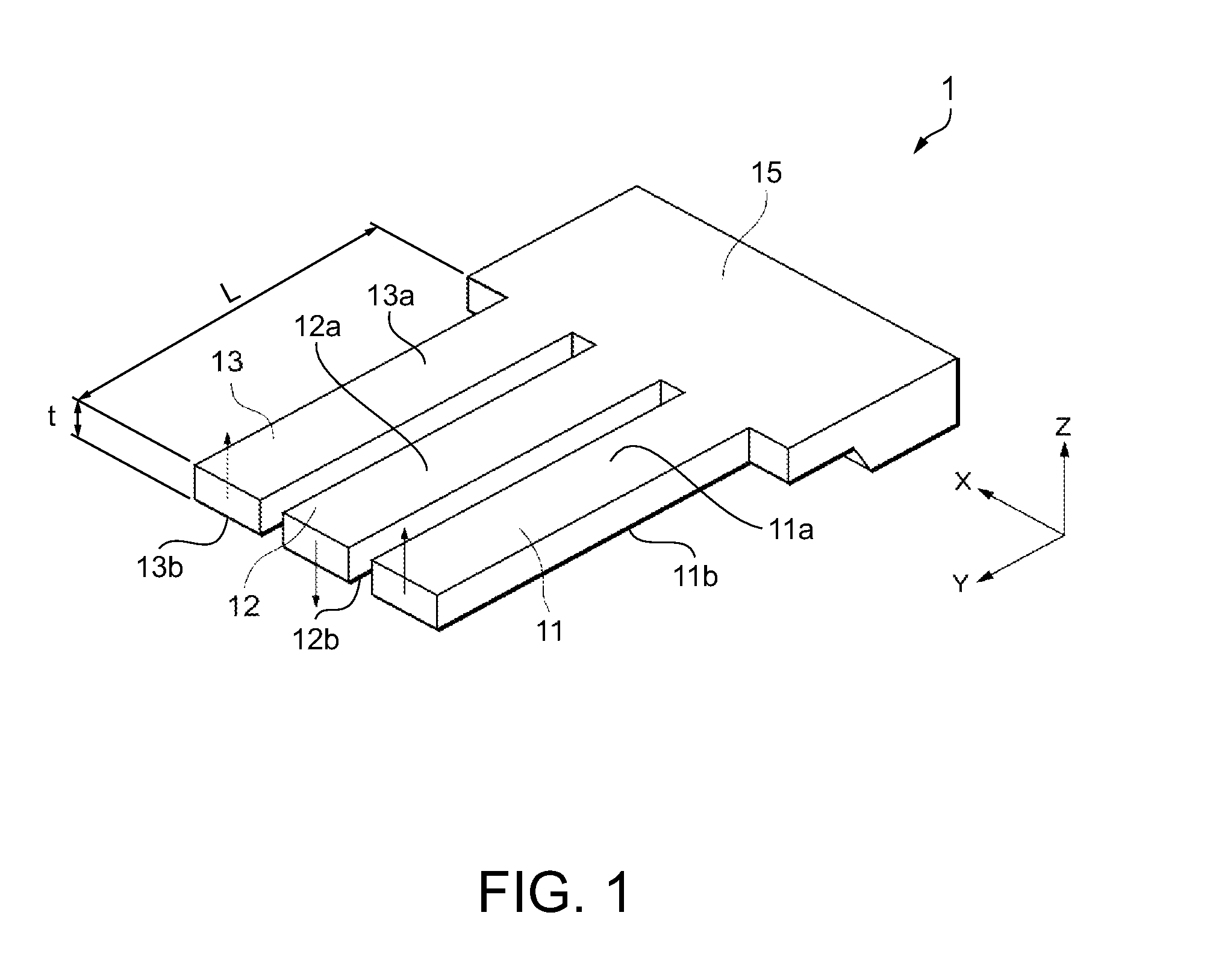
[0069]The resonator element 1 has a shape such that the thickness direction thereof corresponds to the Z direction when it is expanded on the XY plane of an orthogonal coordinate system. The resonator element 1 includes three vibrating arms 11, 12, and 13, and the vibrating arms 11, 12, and 13 are arranged in the X direction, and each vibrating arm extends in parallel in the Y direction. The vibrating arms 11, 12, and 13 are connected to the base portion 15, thus constructing the resonator element 1 in which the respective vibrating arms 11, 12, and 13 have a cantilever structure.

[0070]Piezoelectric elements 61, 62, and 63 are formed at positions of the vibrating arms 11, 12, and 13 close to the...

second embodiment

[0113]Next, a resonator having the above-described resonator element will be described as a second embodiment.

[0114]FIGS. 7A and 7B show a configuration of a resonator, in which FIG. 7A is a schematic top view, and FIG. 7B is a schematic sectional view taken along the line G-G in FIG. 7A.

[0115]A resonator 5 includes the resonator element 1 according to the first embodiment, a ceramic package 81 serving as a container, and a cover 85.

[0116]The ceramic package 81 has a recess portion which is formed so as to accommodate the resonator element 1, and connection pads 88 connected to the mount electrodes of the resonator element 1 are formed in the recess portion. The connection pads 88 are connected to wirings in the ceramic package 81 so as to be conducted to external connection terminals 83 which are provided on the periphery of the ceramic package 81.

[0117]Moreover, a seam ring 82 is provided around the recess portion of the ceramic package 81. Furthermore, a penetration hole 86 is pr...

third embodiment

[0120]Next, an oscillator having the above-described resonator element will be described as a third embodiment.

[0121]FIGS. 8A and 8B show a configuration of an oscillator, in which FIG. 8A is a schematic top view, and FIG. 8B is a schematic sectional view taken along the line H-H in FIG. 8A.

[0122]An oscillator 6 is different from the resonator 5 described above in that it further includes an IC chip as a circuit element. Therefore, the same constituent elements as those of the resonator 5 will be denoted by the same reference numerals, and description thereof will be omitted.

[0123]The oscillator 6 includes the resonator element 1 according to the first embodiment, the ceramic package 81 serving as a container, the cover 85, and an IC chip 91 serving as a circuit element.

[0124]The IC chip 91 includes an oscillation circuit that excites the resonator element 1, and is fixed to the bottom portion of the ceramic package 81 and connected to other wirings by metal wires 92 such as gold wi...


PUM


Abstract

A resonator element includes: a base portion provided on a plane including a first axis and a second axis orthogonal to the first axis; a vibrating arm extending from the base portion in the first axis direction; an excitation electrode provided on the vibrating arm so as to excite the vibrating arm; and a first mass portion provided on the vibrating arm so as to adjust the frequency of the vibrating arm, wherein the vibrating arm performs flexural vibration in a direction perpendicular to the plane and wherein the first mass portion is provided in a region exceeding ½ of the entire length in the first axis direction of the vibrating arm from the end of the vibrating arm close to the base portion and is formed from a material whose density D (in units of 103 kg / m3) is in the range of 2.20≦D≦8.92.

Description

BACKGROUND[0001]1. Technical Field[0002]The present invention relates to a resonator element, a resonator, an oscillator, an electronic device, and a frequency adjustment method.[0003]2. Related Art[0004]In a resonator having a vibrating arm, a resonator element is known in which a vibrating arm vibrates in the thickness direction of the vibrating arm (such a mode of vibration is an out-of-plane mode) rather than vibrating in an in-plane mode. This resonator element generally has an odd number of vibrating arms. When the resonator element has three or more vibrating arms, adjacent vibrating arms perform walk-mode vibration in which they repeatedly vibrate alternately in opposing directions.[0005]Adjustment of the frequency of a tuning-fork type resonator that vibrates in an in-plane mode is performed by providing a weight on a plane in the vibration direction of the tip end of a vibrating arm and irradiating the weight with laser light or the like to remove a part of the weight. Thi...

Claims


Application Information

Patent Timeline
Patent Type & Authority Patents(United States)
IPC IPC(8): H03H9/21H03H9/05H03H9/10H03H3/04
CPCH03H2003/0492H03H9/21H03H9/1021H03H9/0547
Inventor KAWAI, HIROKI
Owner SEIKO EPSON CORP
Learn More