Resonator element, resonator, oscillator, electronic device, and frequency adjsutment method
a technology of resonator and oscillator, which is applied in the direction of piezoelectric/electrostrictive/magnetostrictive devices, piezoelectric/electrostrictive device details, oscillator generators, etc., can solve the problems of difficult frequency adjustment, difficult to add a weight on the side surfaces of a thin vibrating arm to perform frequency adjustment of resonator elements, and difficult laser light to remove a part of the weight, etc., to prevent
- Summary
- Abstract
- Description
- Claims
- Application Information
AI Technical Summary
Benefits of technology
Problems solved by technology
Method used
Image
Examples
first embodiment
FIGS. 4A to 4C show a configuration of a resonator element according to a first embodiment, in which FIG. 4A is a schematic top view, FIG. 4B is a schematic sectional view taken along the line A-A in FIG. 4A, and FIG. 4C is a schematic sectional view taken along the line B-B in FIG. 4A.
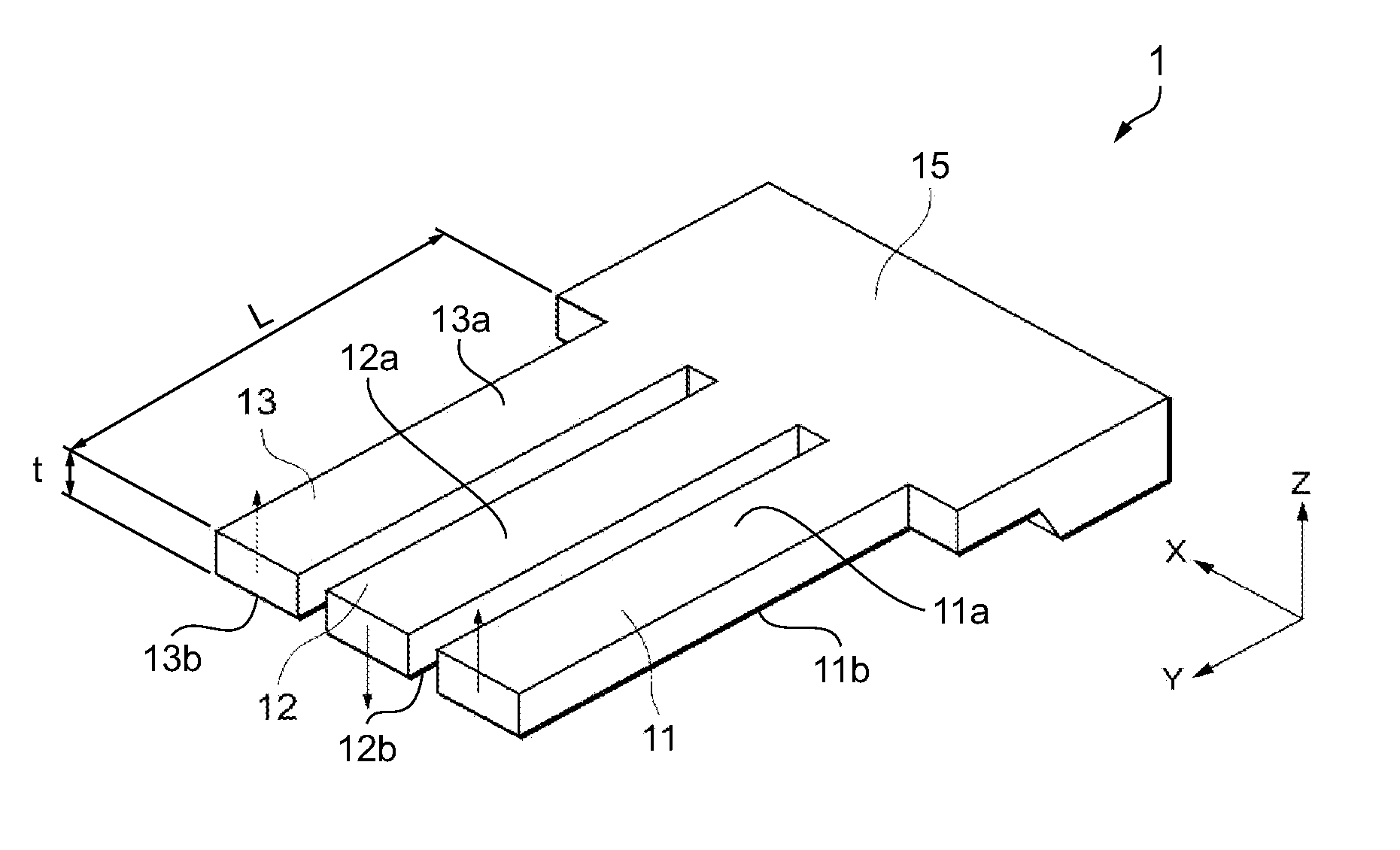
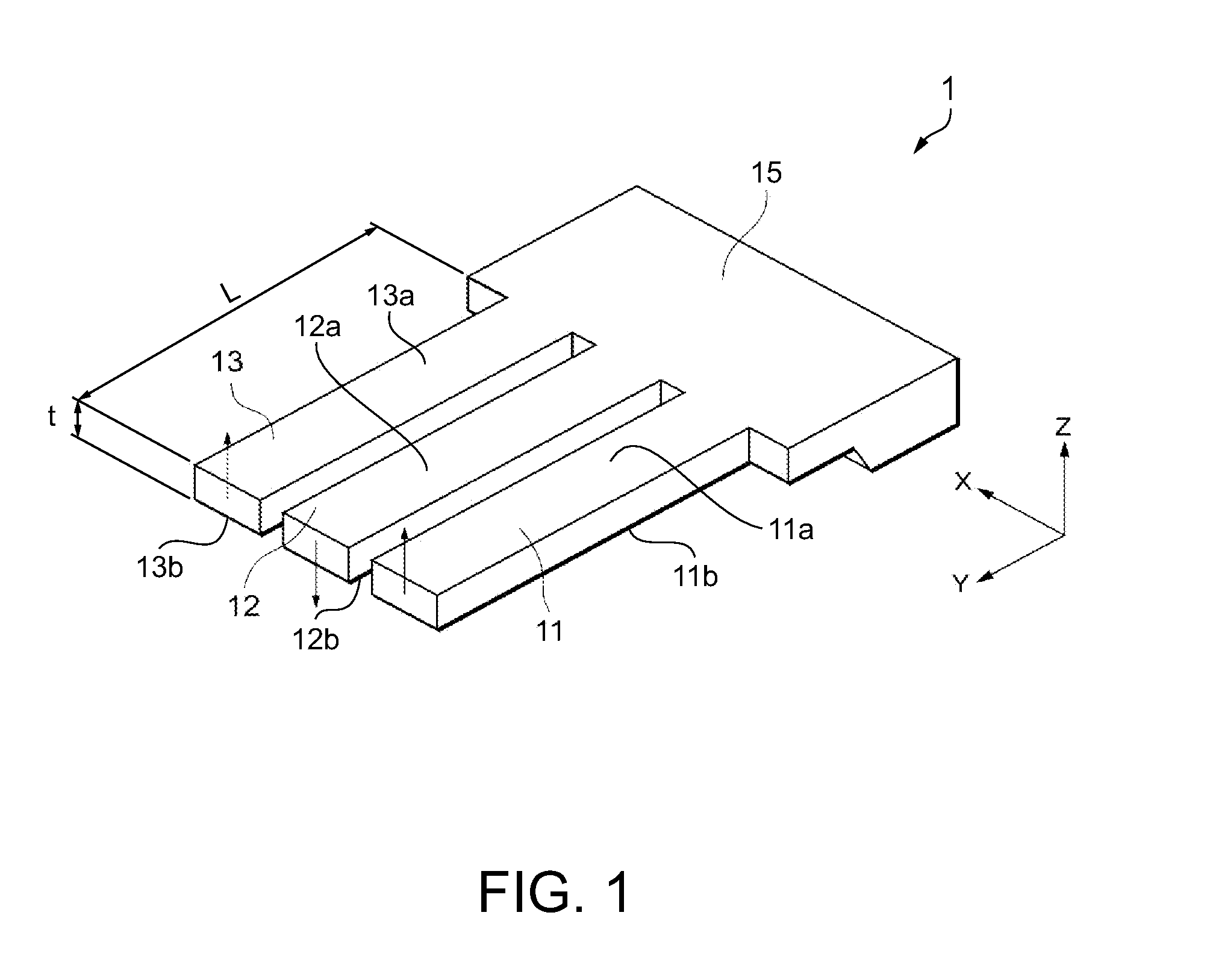
The resonator element 1 has a shape such that the thickness direction thereof corresponds to the Z direction when it is expanded on the XY plane of an orthogonal coordinate system. The resonator element 1 includes three vibrating arms 11, 12, and 13, and the vibrating arms 11, 12, and 13 are arranged in the X direction, and each vibrating arm extends in parallel in the Y direction. The vibrating arms 11, 12, and 13 are connected to the base portion 15, thus constructing the resonator element 1 in which the respective vibrating arms 11, 12, and 13 have a cantilever structure.
Piezoelectric elements 61, 62, and 63 are formed at positions of the vibrating arms 11, 12, and 13 close to the base portion 15, ...
second embodiment
Next, a resonator having the above-described resonator element will be described as a second embodiment.
FIGS. 7A and 7B show a configuration of a resonator, in which FIG. 7A is a schematic top view, and FIG. 7B is a schematic sectional view taken along the line G-G in FIG. 7A.
A resonator 5 includes the resonator element 1 according to the first embodiment, a ceramic package 81 serving as a container, and a cover 85.
The ceramic package 81 has a recess portion which is formed so as to accommodate the resonator element 1, and connection pads 88 connected to the mount electrodes of the resonator element 1 are formed in the recess portion. The connection pads 88 are connected to wirings in the ceramic package 81 so as to be conducted to external connection terminals 83 which are provided on the periphery of the ceramic package 81.
Moreover, a seam ring 82 is provided around the recess portion of the ceramic package 81. Furthermore, a penetration hole 86 is provided on the bottom portion o...
third embodiment
Next, an oscillator having the above-described resonator element will be described as a third embodiment.
FIGS. 8A and 8B show a configuration of an oscillator, in which FIG. 8A is a schematic top view, and FIG. 8B is a schematic sectional view taken along the line H-H in FIG. 8A.
An oscillator 6 is different from the resonator 5 described above in that it further includes an IC chip as a circuit element. Therefore, the same constituent elements as those of the resonator 5 will be denoted by the same reference numerals, and description thereof will be omitted.
The oscillator 6 includes the resonator element 1 according to the first embodiment, the ceramic package 81 serving as a container, the cover 85, and an IC chip 91 serving as a circuit element.
The IC chip 91 includes an oscillation circuit that excites the resonator element 1, and is fixed to the bottom portion of the ceramic package 81 and connected to other wirings by metal wires 92 such as gold wires.
Give the above, since the ...
PUM
 Abstract
Description
Claims
Application Information
 - R&D
- Intellectual Property
- Life Sciences
- Materials
- Tech Scout
- Unparalleled Data Quality
- Higher Quality Content
- 60% Fewer Hallucinations
Browse by: Latest US Patents, China's latest patents, Technical Efficacy Thesaurus, Application Domain, Technology Topic, Popular Technical Reports.
© 2025 PatSnap. All rights reserved.Legal|Privacy policy|Modern Slavery Act Transparency Statement|Sitemap|About US| Contact US: help@patsnap.com


