Hair dryer having a passive silencer system
a technology of silencer and hair dryer, which is applied in the direction of resistor details, hair drying, hair cleaning, etc., can solve the problems of user not being able to hear directly airflow and turbine, and achieve the effects of reducing the noise associated, and reducing the generation of turbulen
- Summary
- Abstract
- Description
- Claims
- Application Information
AI Technical Summary
Benefits of technology
Problems solved by technology
Method used
Image


Examples
first embodiment
[0050]FIG. 1 schematically illustrates a hair dryer 1 comprising a plastic shell 10 and a stem 11 forming a handle. According to the conventional operation of a hair dryer, the plastic shell 10 comprises an air inlet EA and an air outlet SA. In this embodiment, the air inlet EA illustrated by an arrow is made at the end of the handle stem 11.
[0051]On the air circuit, a space 12, also called a suction chamber, is then found, preceding an internal structure 13 bearing a fan not shown which pulses the air towards the air outlet SA also illustrated by an arrow. Conventionally and in the whole of the embodiments shown, heating means 20 are placed on the path of the air pulsed by the fan. These preheating means are advantageously profiled as illustrated in FIG. 1 in order to limit the generation of turbulences and therefore the generation of noise. This is all the more important since a rise in temperature increases the generation of turbulences.
[0052]In this embodiment, the motor is adva...
second embodiment
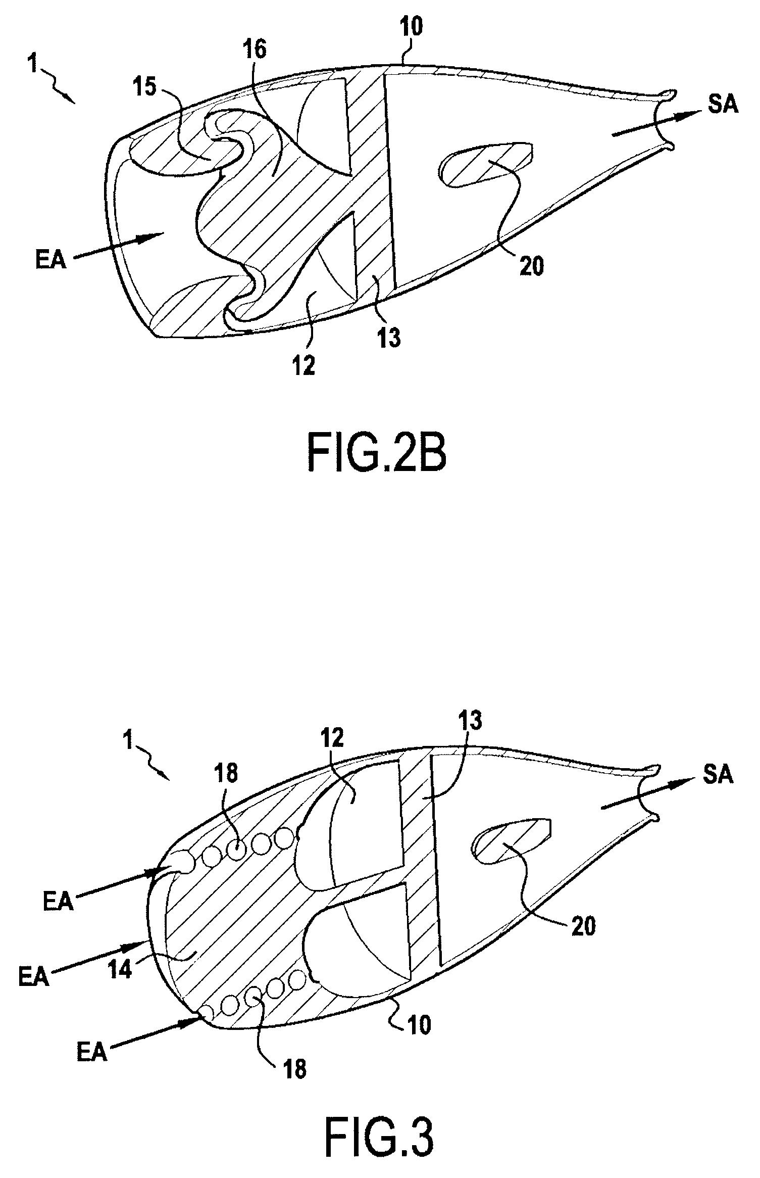
[0053]FIGS. 2A and 2B illustrate two alternatives of a same second embodiment of a hair dryer according to the invention. The hair dryer 1 here comprises a tapered plastic shell 10 with an air inlet EA and an air outlet SA. The air inlet EA is placed at the rear end of the fuselage 10. Before a space 12, also called a suction chamber, preceding an internal structure 13 bearing a fan 13, a baffle is directly conformed by molding of the actual plastic shell. This baffle is made by specific molding of a profile on the internal face of the fuselage 10 and of a mating profile at an internal projection of the plastic shell 10 borne by the internal structure 13 bearing the fan, both of these moldings being achieved with rotational symmetry.
[0054]Thus, on the internal face of the fuselage 10 is molded a lip 15 with rotational symmetry turned towards the rear of the fuselage. This lip 15 has a profile mating a baffle front 16, acting as a protective cap at the rear end of the fuselage 10. Th...
third embodiment
[0059]FIG. 3 represents the invention according to which the plastic cap 14, placed at the rear end of the plastic shell 10, is pierced with at least one spiral channel 18 and preferably with several spirals, here four spirals. The air inlet EA then consists of the inlet(s) of this(these) spiral(s). The air then circulating in its spirals sees its acoustic path extended as compared with the direct rectilinear path of an inlet placed at the rear end of the fuselage 10 and the space 12.
[0060]Circulation of air in the spirals 18 is laminar circulation of air which avoids generation of turbulences and the associated noise. Moreover, by multiplying the number of spirals, it is possible to limit the pressure losses. This allows the use of a not very large spiral channel diameter while ensuring that the pressure losses are not significant. In any case, by using a suitable spiral channel diameter with a suitable number of spirals it is possible to not observe any pressure drop or observe mi...
PUM
 Abstract
Description
Claims
Application Information
 - R&D
- Intellectual Property
- Life Sciences
- Materials
- Tech Scout
- Unparalleled Data Quality
- Higher Quality Content
- 60% Fewer Hallucinations
Browse by: Latest US Patents, China's latest patents, Technical Efficacy Thesaurus, Application Domain, Technology Topic, Popular Technical Reports.
© 2025 PatSnap. All rights reserved.Legal|Privacy policy|Modern Slavery Act Transparency Statement|Sitemap|About US| Contact US: help@patsnap.com