Spraying heat exchange system of low-temperature multi-effect seawater desalting device

A heat exchange system, low temperature technology, applied in seawater treatment, heat exchanger type, heat exchanger shell, etc., can solve the problems of inability to replace, difficult inspection and maintenance of heat exchange tubes, and difficulty in inspection, to avoid thermal efficiency. The effect of reducing and improving equipment utilization and improving heat utilization efficiency

Pending Publication Date: 2020-08-11
TIANJIN SDIC JINNENG ELECTRIC POWER
View PDF0 Cites 0 Cited by
  • Summary
  • Abstract
  • Description
  • Claims
  • Application Information

AI Technical Summary

Problems solved by technology

[0006] (1) The existing technology involves low-temperature multi-effect seawater desalination devices. Due to the complex internal structure, each effect body is usually welded or flanged. It is difficult to check and maintain the heat exchange tubes inside the effect, and they are usually removed separately
[0007] (2) The prior art involves the low-temperature multi-effect seawater desalination device. During the long-term operation of the device, part of the heat exchange tubes are corroded. Since they cannot be dismantled separately, it is usually difficult to inspect and cannot be replaced. Affect the normal heat exchange of the system
[0008] (3) The existing technology involves low-temperature multi-effect seawater desalination equipment. Due to long-term operation, scaling and salt accumulation occur on the outer wall of the heat exchange tube. Due to the narrow gap between the tubes, it cannot be washed or completely removed by chemical cleaning under normal conditions.
[0010] (5) Due to the large number of pipes and the large overall weight of the spray heat exchange pipes of the seawater desalination device involved in the prior art, stricter requirements are pla...

Method used


Image

  • Spraying heat exchange system of low-temperature multi-effect seawater desalting device
  • Spraying heat exchange system of low-temperature multi-effect seawater desalting device
  • Spraying heat exchange system of low-temperature multi-effect seawater desalting device

Examples


Embodiment Construction

[0041] The technical solutions of the present invention will be clearly and completely described below in conjunction with the accompanying drawings. Apparently, the described embodiments are some of the embodiments of the present invention, but not all of them. Based on the embodiments of the present invention, all other embodiments obtained by persons of ordinary skill in the art without making creative efforts belong to the protection scope of the present invention.

[0042] In the description of the present invention, it should be noted that the terms "center", "upper", "lower", "left", "right", "vertical", "horizontal", "inner", "outer" etc. The indicated orientation or positional relationship is based on the orientation or positional relationship shown in the drawings, and is only for the convenience of describing the present invention and simplifying the description, rather than indicating or implying that the referred device or element must have a specific orientation, ...


PUM


Abstract

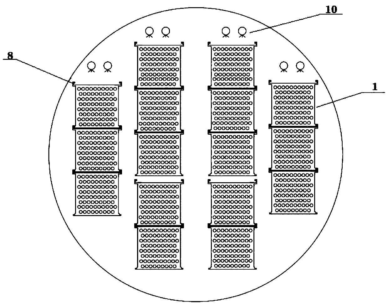
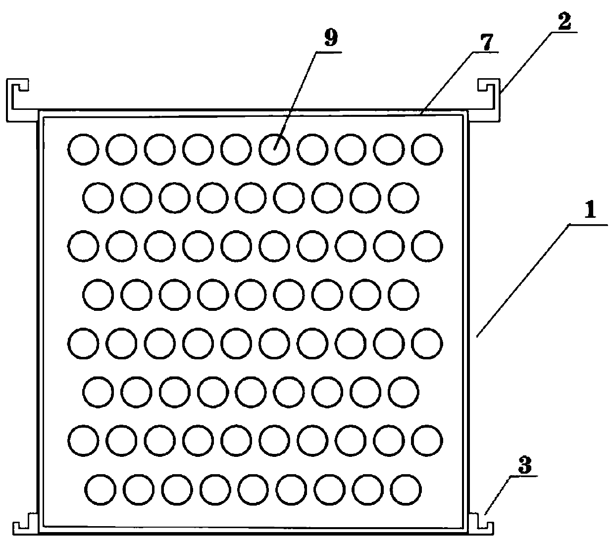
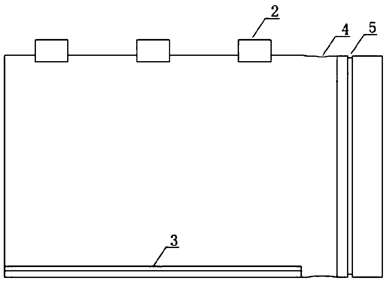
The invention designs a spraying heat exchange system of a low-temperature multi-effect seawater desalting device. The spraying heat exchange system is characterized by comprising a plurality of heatexchange tube bundle modules and a plurality of spraying tube bundle modules, wherein hangers and slide slots are arranged on the outer walls of the heat exchange tube bundle modules; the multiple heat exchange tube bundle modules are connected up and down through the hangers and the slide slots which are matched with one another; the front ends of the heat exchange tube bundle modules are provided with front end walls, and the rear ends of the heat exchange tube bundle modules are provided with rear end walls; and the heat exchange tube bundle modules are connected front and rear through thefront end walls and the rear end walls which are mutually matched. The spraying heat exchange system adopts a modularized design, is convenient in mounting, is simple in operation, saves labor and power, can be independently dismounted and maintained, is convenient in maintenance, shortens a maintenance period, and increases an equipment utilization rate.

Description

technical field [0001] The invention relates to a heat exchange system applied in seawater desalination, in particular to a spray heat exchange system for a low-temperature multi-effect seawater desalination device. Background technique [0002] The low-temperature multi-effect seawater desalination device is a thermal seawater desalination process with many commercial cases at present. It is characterized in that a series of evaporators (referred to as effects) containing spray tube bundles are connected in series, and a certain amount of steam is input into the inside of the heat exchange tube. , a certain amount of pretreated seawater is sprayed on the upper part of the tube. After heat exchange, the seawater becomes secondary steam and enters the next effect. The steam in the tube is collected after being condensed by seawater heat exchange. After repeated evaporation and condensation in the device, The process of obtaining desalinated water that is many times the amount...

Claims


Application Information

Patent Timeline
IPC IPC(8): F28D3/04F28F9/26C02F1/04C02F103/08
CPCC02F1/04C02F2103/08F28D3/04F28F9/26Y02A20/124
Inventor 依庆文邢兆强苏大鹏韩志杰
Owner TIANJIN SDIC JINNENG ELECTRIC POWER
Why Eureka
Try Eureka