Multipoint converters with brake chopper

a technology of multi-point converters and converters, applied in the direction of power conversion systems, electrical apparatus, dynamo-electric motors/converter stoppers, etc., can solve the problems of power converters being incapable of feeding energy back into the grid, power converters may be incapable of occupying excess energy, and excessive voltage increases

Active Publication Date: 2014-11-04
GE ENERGY POWER CONVERSION
View PDF5 Cites 1 Cited by
  • Summary
  • Abstract
  • Description
  • Claims
  • Application Information

AI Technical Summary

Benefits of technology

[0008]Another embodiment of the present invention is a method for operating an electrical circuit to control operation of a power converter such that operation of the power converter controls a current flowing through a brake resistance within the electrical circuit. The power converter includes two parallel circuit structures. Each parallel circuit structure includes at least one semiconductor switch, at least one connection node and at least one energy storage device. A brake resistance is switched in an open position and disposed between the connection nodes of the two parallel circuit structures. The brake resistance is connected to the semiconductor switch of each parallel circuit structure at respective connection points. The method includes applying power to the brake resistance and reducing the power in the brake resistance via redundant switching states provided within the parallel circuit structures.
[0005]One conventional brake chopper has a modular design with distributed brake resistances. By allocating the brake resistance to a power electronics module, it is possible to achieve a modular structure and distribute the braking performance into several such modules. However, semiconductor switches are generally necessary for controlling the brake chopper circuit which is needed in addition to the semiconductor switches in the power converter in order to ensure the functioning of the brake chopper. As a result, the prevention or reduction of the excess voltage adds complexity to the circuitry and increases costs. Therefore, an improved electrical circuit that facilitates the prevention or reduction of excess voltage within a power converter would be useful.
[0014]FIG. 3A provides a schematic wiring diagram of an electrical circuit for a power converter branch including parallel circuit structures according to one embodiment of the present invention;
[0005]One conventional brake chopper has a modular design with distributed brake resistances. By allocating the brake resistance to a power electronics module, it is possible to achieve a modular structure and distribute the braking performance into several such modules. However, semiconductor switches are generally necessary for controlling the brake chopper circuit which is needed in addition to the semiconductor switches in the power converter in order to ensure the functioning of the brake chopper. As a result, the prevention or reduction of the excess voltage adds complexity to the circuitry and increases costs. Therefore, an improved electrical circuit that facilitates the prevention or reduction of excess voltage within a power converter would be useful.
[0007]One embodiment of the present invention is an electrical circuit for a power converter. The power converter includes two parallel circuit structures. Each parallel circuit structure includes at least one semiconductor switch, at least one connection node and at least one energy storage device. A brake resistance is disposed between the connection nodes of the two parallel circuit structures. The brake resistance is connected to the semiconductor switch of each parallel circuit structure at a respective connection points such that operation of the power converter controls a current flowing through the brake resistance.
[0008]Another embodiment of the present invention is a method for operating an electrical circuit to control operation of a power converter such that operation of the power converter controls a current flowing through a brake resistance within the electrical circuit. The power converter includes two parallel circuit structures. Each parallel circuit structure includes at least one semiconductor switch, at least one connection node and at least one energy storage device. A brake resistance is switched in an open position and disposed between the connection nodes of the two parallel circuit structures. The brake resistance is connected to the semiconductor switch of each parallel circuit structure at respective connection points. The method includes applying power to the brake resistance and reducing the power in the brake resistance via redundant switching states provided within the parallel circuit structures.

Problems solved by technology

However, an energy sink connected to the power converter may be unable to take up excess energy (e.g. a power supply grid in case of a short circuit) or that the power converter may be incapable of feeding energy back into the grid because of its design.
In power converters with a voltage source inverter, this could lead to an excessive increase of the voltage source and thus, the power must be lowered.
As a result, the prevention or reduction of the excess voltage adds complexity to the circuitry and increases costs.

Method used


Image

  • Multipoint converters with brake chopper
  • Multipoint converters with brake chopper
  • Multipoint converters with brake chopper

Examples


Embodiment Construction

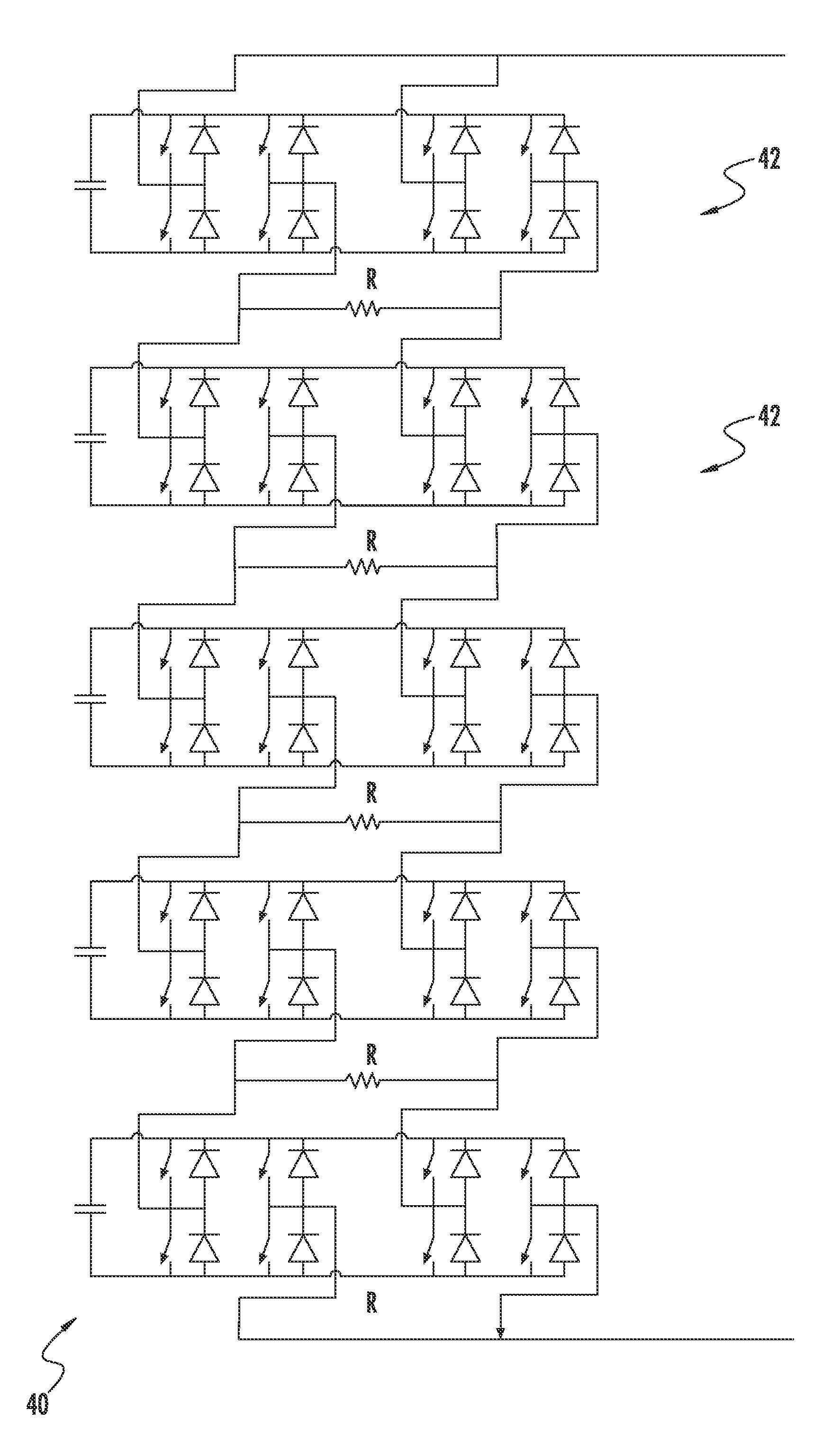
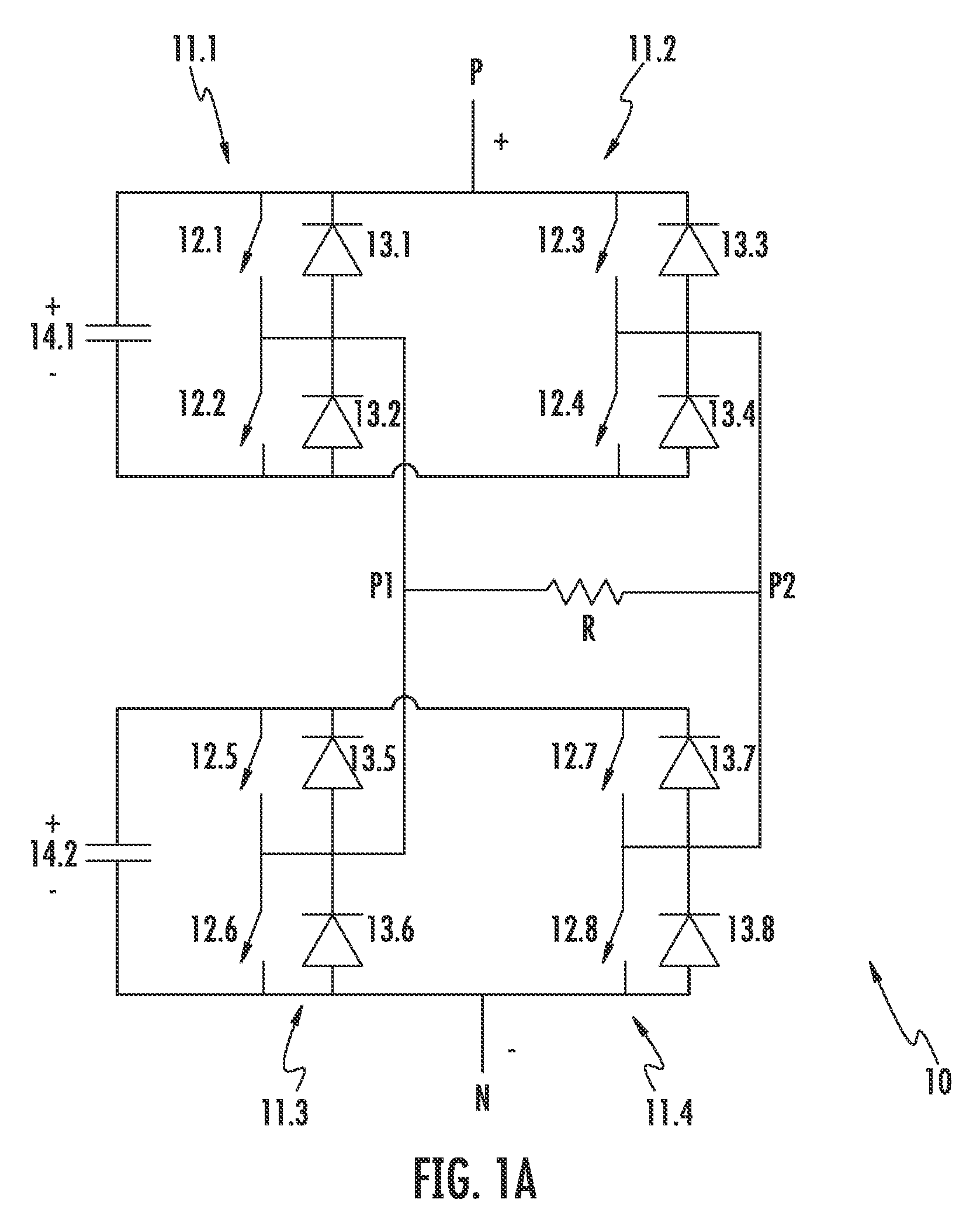
[0018]FIG. 2 shows a three-phase representation of a modular multi-point power converter 20. This type of multi-point power converter is also known as modular multilevel converter (M2C). In one embodiment, every one of the three phases of the power converter 20 consists of two parallel circuit structures. Furthermore, every one of the three phases is made up of a number of power converter subsystems 10. In this embodiment each of the three phases consists of four power converter subsystems 10 per phase. One of these power converter subsystems will be explained in more detail below with the help of FIGS. 1A and 1B.

[0019]In one embodiment, as shown in FIGS. 1A and 1B, the power converter subsystems 10 contain the parallel circuit structures. The semiconductor switches of every power converter subsystem and all power converter subsystems jointly serve for controlling the operation of the power converter 20. The semiconductor switches of every single power converter subsystem 21 serve s...


PUM


Abstract

An electrical circuit for a power converter is described. The circuit has been provided with several semiconductor switches and capacitors used for operating the power converter. A brake resistance for lowering energy is provided and is connected to the semiconductor switches provided without the need for an additional switch. The operation of the power converter and the current flowing through the brake resistance can be controlled by means of the existing semiconductor switches.

Description

FIELD OF THE INVENTION[0001]The present invention generally refers to an electrical circuit for a power converter. More specifically, the present invention relates to an electrical circuit that facilitates the prevention or reduction of excess voltage within a power converter.BACKGROUND OF THE INVENTION[0002]With power converters, it may become necessary to convert excess energy into heat. There can be many situations where this is necessary. For example, an energy source (such as a wind power station) may be connected to a power converter to supply energy to the power converter. However, an energy sink connected to the power converter may be unable to take up excess energy (e.g. a power supply grid in case of a short circuit) or that the power converter may be incapable of feeding energy back into the grid because of its design. In power converters with a voltage source inverter, this could lead to an excessive increase of the voltage source and thus, the power must be lowered.[000...

Claims


Application Information

Patent Timeline
Patent Type & Authority Patents(United States)
IPC IPC(8): H02M7/483H02M7/217H02M7/219H02M7/5387H02P3/22
CPCH02M7/483H02M7/217H02P3/22H02M7/219H02M1/32Y02E10/76H02M2007/4835H02M7/4835
Inventor JAKOB, ROLANDBRUCKNER, THOMAS
Owner GE ENERGY POWER CONVERSION
Why Eureka
Try Eureka