
Wireless communication device

a communication device and wireless technology, applied in the field of wireless communication devices, can solve the problems of increasing the loss caused by the material of the pattern conductor or the dielectric substrate, increasing the insertion loss, and increasing the variation of the capacitance of the capacitance element, so as to achieve significant reduction or prevention of insertion loss, and difficult to achieve capacitance variation.

Active Publication Date: 2014-11-04
MURATA MFG CO LTD
View PDF707 Cites 6 Cited by
  • Summary
  • Abstract
  • Description
  • Claims
  • Application Information

AI Technical Summary

Benefits of technology

The present invention provides a wireless communication device with reduced insertion loss and prevention of variations in capacitance even when a dielectric layer is misaligned.

Problems solved by technology

However, in the above-described wireless communication device, the coil patterns (pattern conductors) are formed in the multilayer substrate, resulting in a first problem in that loss caused by a material of the pattern conductors or dielectric substrates is apt to increase.
Especially when the size of the multilayer substrate is to be reduced, it is necessary, for example, to narrow the line width of a coil pattern in order to obtain a desired inductance value, causing the insertion loss to be further increased.
The above-described wireless communication device has a second problem in that misalignment of a dielectric layer causes variations in the capacitance of the capacitance element in the multilayer substrate.

Method used


Image

  • Wireless communication device
  • Wireless communication device
  • Wireless communication device

Examples


Embodiment Construction

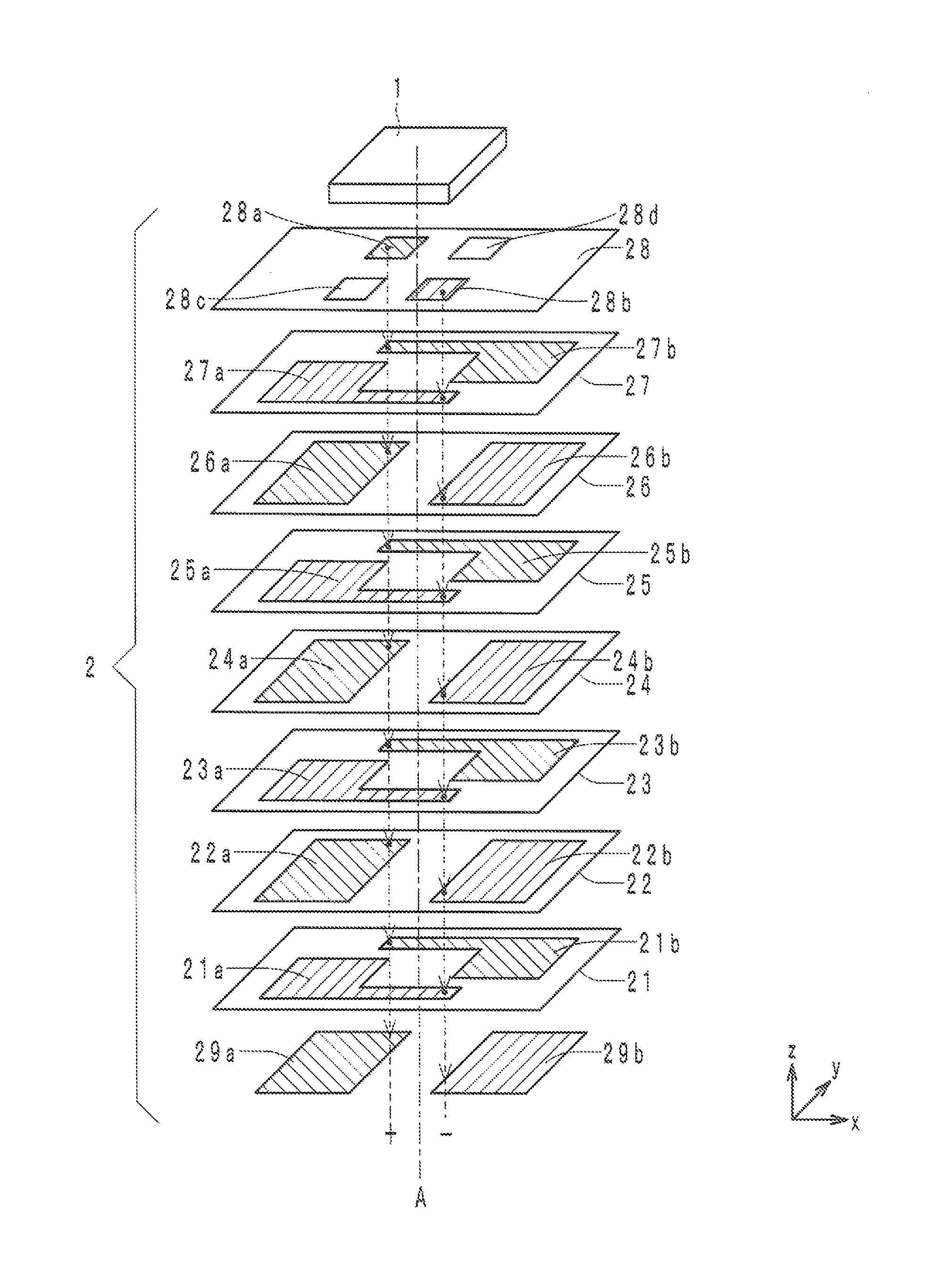
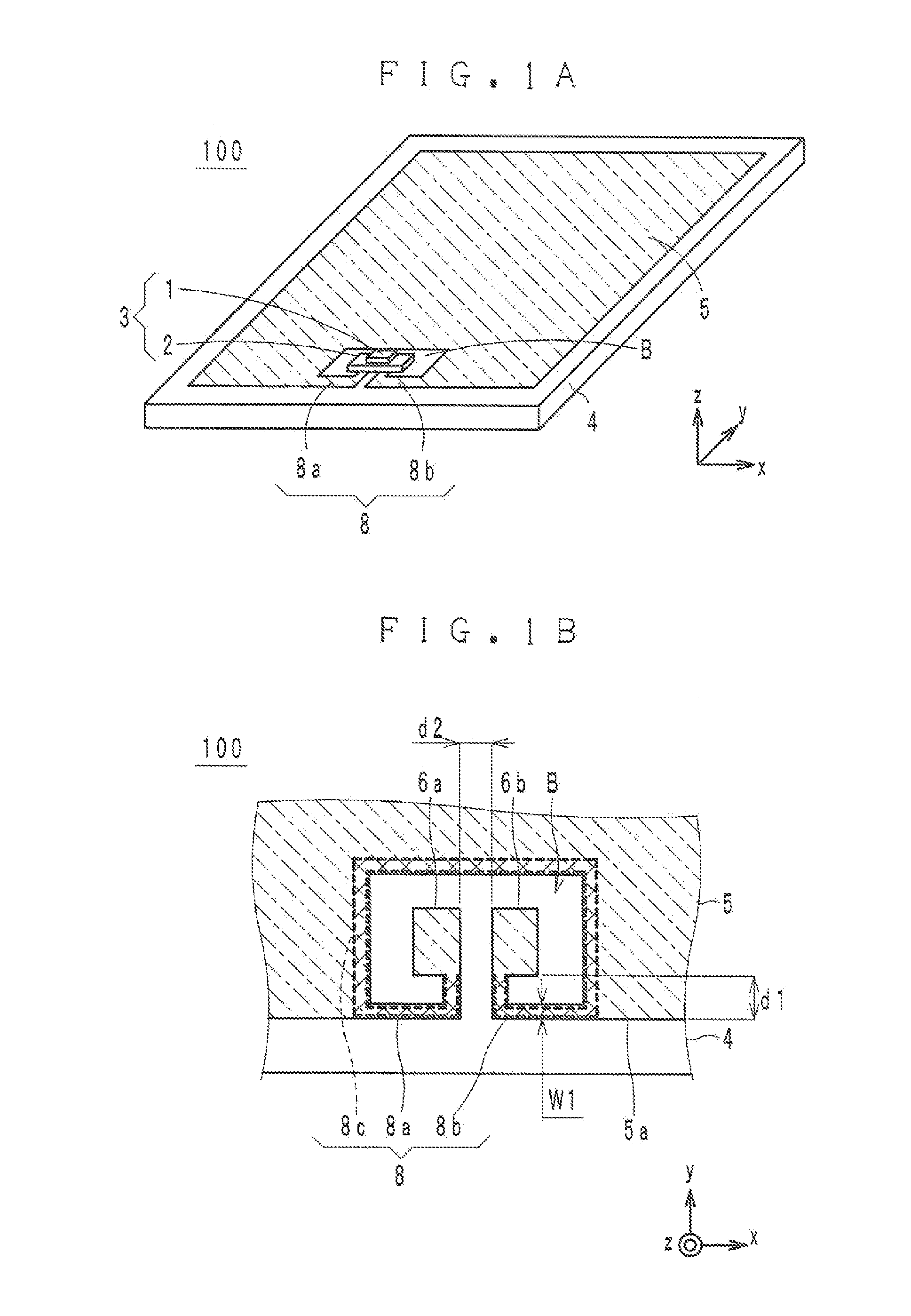
[0026]For convenience of description below, arrows x, y, and z used in some of the drawings are defined. The arrows x and y indicate the left-right direction and the front-back direction of a wireless communication device, respectively. The arrow z indicates the up-down direction of the wireless communication device, and also indicates the stacking direction of a multilayer substrate.

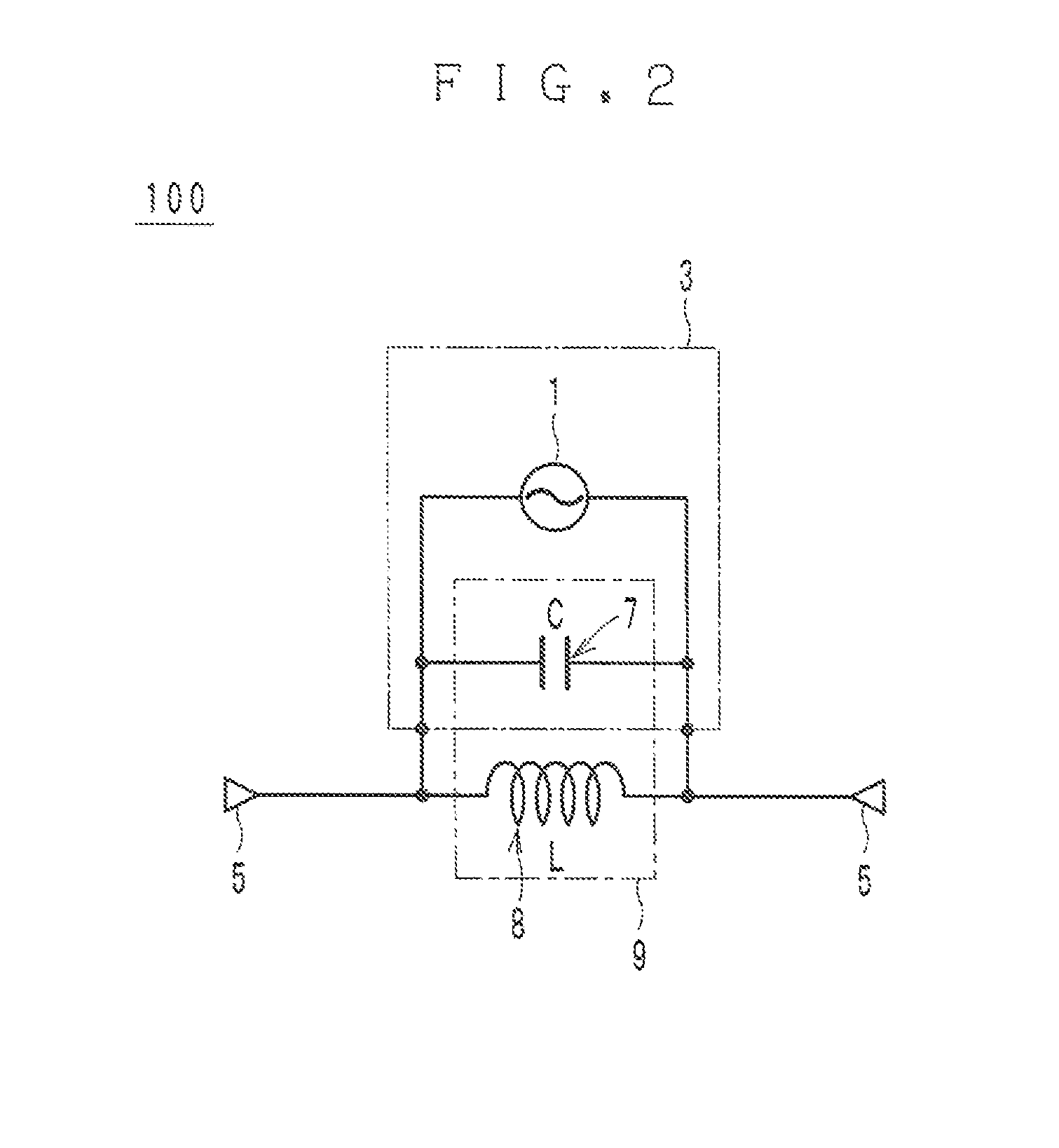
[0027]Referring to FIGS. 1A to 5, a wireless communication device 100 according to a preferred embodiment of the present invention will be described in detail. The wireless communication device 100 preferably is, for example, an RFID tag used in a UHF band RFID system. A carrier frequency in 900 MHz band is used in a UHF band RFID system. A UHF band RFID system has characteristics of having a long communication distance and being capable of simultaneously reading out pieces of information of multiple RFID tags. Therefore, a UHF band RFID system has been a promising system for commodity management. The w...


PUM


Abstract

A wireless communication device includes a wireless IC device, a multilayer substrate including a stack of a plurality of dielectric layers, a resonant circuit that is connected to the wireless IC device and that includes a capacitance element provided in the multilayer substrate and an inductance element provided outside the multilayer substrate, and a radiation conductor connected to the resonant circuit.

Description

[0001]This application claims priority to Japanese Patent Application No. 2011-155294 filed on Jul. 14, 2011 and International Patent Application No. PCT / JP2012 / 067779 filed on Jul. 12, 2012, the entire disclosures of which are incorporated herein by reference.BACKGROUND OF THE INVENTION[0002]1. Field of the Invention[0003]The present invention relates to a wireless communication device including a resonant circuit connected to a wireless IC device and a radiation conductor connected to the resonant circuit.[0004]2. Description of the Related Art[0005]Recently, radio frequency identification (RFID) systems have been used for various applications such as commodity management. An RFID system includes a reader / writer and an RFID tag. To transmit information to each other through non-contact communication, a reader / writer and an RFID tag each include a wireless IC device (i.e., RFID IC chip) and a radiation conductor (i.e., antenna).[0006]When information is to be transmitted, the wirel...

Claims


Application Information

Patent Timeline
Patent Type & Authority Patents(United States)
IPC IPC(8): H04B5/00H01Q7/00H01Q1/22H01Q1/38H01Q1/48H01Q9/06H04B5/48
CPCH01Q7/00H01Q1/2225H04B5/0075H01Q9/06H01Q1/38H01Q1/48H04B5/0062G06K19/07722G06K19/07754G06K19/0726H04B5/77H04B5/24G06K19/07
Inventor DOKAI, YUYA
Owner MURATA MFG CO LTD
Learn More