
Method of transforming a doppler velocity dataset into a velocity vector field

dataset technology, applied in the field of transforming a doppler velocity dataset into a velocity vector field, can solve the problems of large equipment requirements, inability to use in clinical routines, and inability to achieve high frame rate calculation, so as to achieve stable, reproducible and accurate calculation of the velocity vector field

Active Publication Date: 2014-10-14
TOMTEC IMAGING SYST +1
View PDF3 Cites 4 Cited by
  • Summary
  • Abstract
  • Description
  • Claims
  • Application Information

AI Technical Summary

Benefits of technology

The invention provides a method for accurately calculating the velocity vector field from Doppler velocity data. This is possible because the elliptic equation allows for the insertion of physically consistent boundary conditions. The solution can also be performed in a new set of Cartesian coordinates that reflect the 2D or 3D effective geometric proportions, which makes the calculations more efficient and uniform. Overall, this method provides a reliable and accurate way to calculate the velocity vector field.

Problems solved by technology

These methods based on MRI require substantial large equipments and are not of practical use in clinical routine.
In addition, flow calculation requires an acquisition at high frame rate that cannot normally be achieved in MRI.
However, Doppler echography has a fundamental limitation: it can measure the velocity along the direction of a scanline, it detects the value of velocity at which blood is moving towards or away from the transducer, but Doppler measurements are blind to motion in the direction transversal to a scanline.
Novel methods, still based on the Doppler effect, are being introduced to evaluate the velocity vector, however these methods require multiple transducers and are not a practical use.
These methods suffer of an intrinsic limitation on the velocity range, and especially they present an important underestimation of large velocities, therefore they are adequate to evaluate streamlines, but they do not allow to properly quantify velocities and the quantities that can be derived from it (Kheradvar et al 2010).
Unfortunately, the integration (2) gives the solution apart from an undetermined function of the radial coordinate and of time.
In fact, the direct use of (2) gives unrealistic values because incompressibility is not exact, due to the presence of a third cross-plane component, and the use of a first order integration (2) eventually provokes the accumulation of all the errors.
Thus, these existing methods present two principal drawbacks:The conceptual drawback that the continuity equation cannot be satisfied, therefore the solution Vθ(r, θ) is—in fact—defined up to an arbitrary function f(r,θ) that may completely alter the solution.
The existing methods essentially suggest a, still arbitrary, choice to define the shape of such a function.The methodological drawback that the solution is found by integration along each sector separately: the solution at one radial position is computed independently from the solution at another radial position.

Method used


Image

  • Method of transforming a doppler velocity dataset into a velocity vector field
  • Method of transforming a doppler velocity dataset into a velocity vector field
  • Method of transforming a doppler velocity dataset into a velocity vector field

Examples


Embodiment Construction

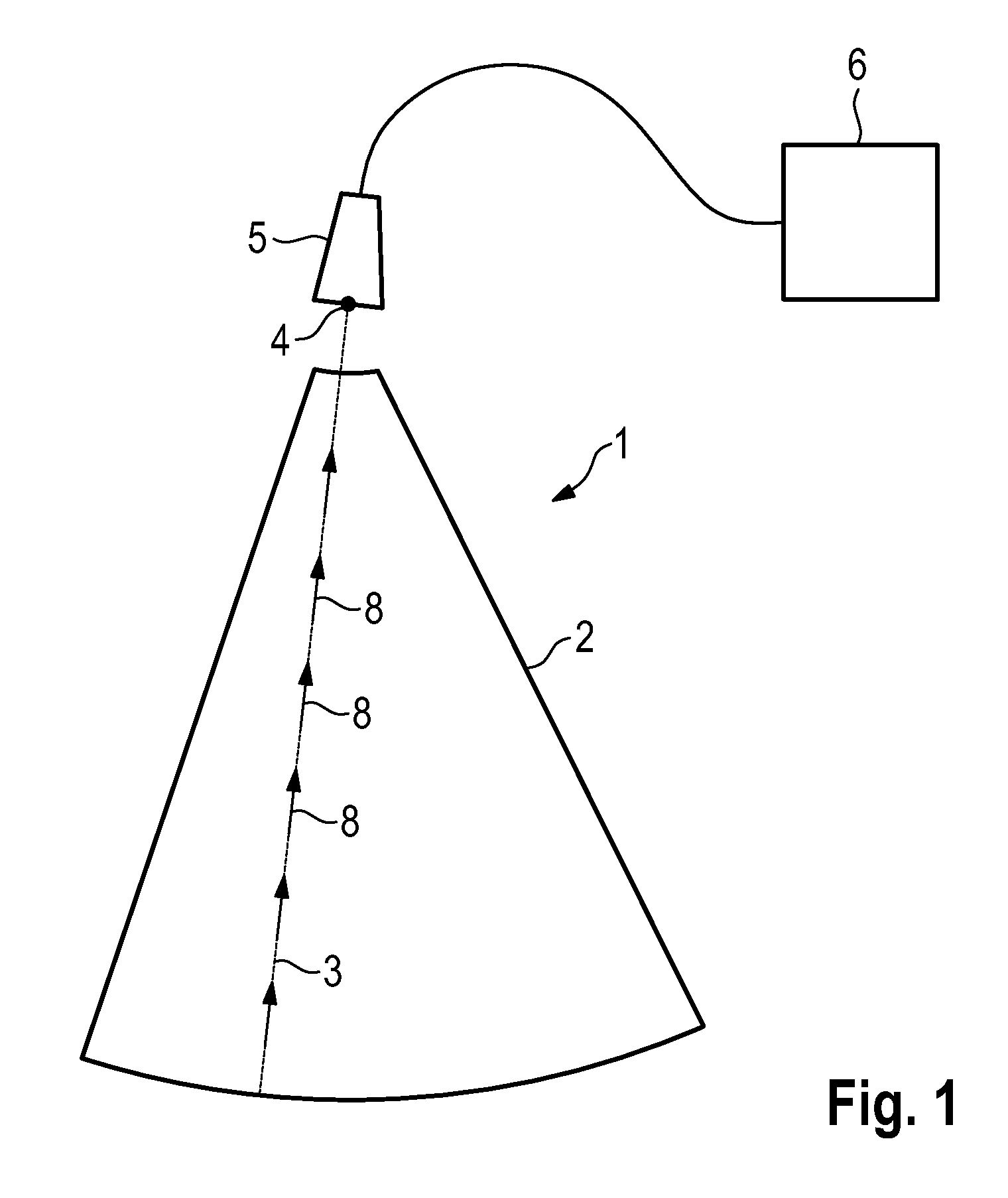
[0053]FIG. 1 is a schematic plan view of a 2D Doppler velocity dataset 1, acquired by means of an ultrasound probe 5 connected to an ultrasound device 6. The conical sector 2 represents the acquisition space or field-of-view, and the Doppler velocity is acquired along all scan-lines 3, which are lines emanating from point 4 on probe 5. One scan-line 3 is shown and a few exemplary Doppler velocity 8 are drawn on top in the shape of arrows.

[0054]As stated above, Doppler ultrasound is capable only of measuring the velocity component in the direction of the scan-line. The transverse velocity has to be estimated, which may be done by means of the inventive method.

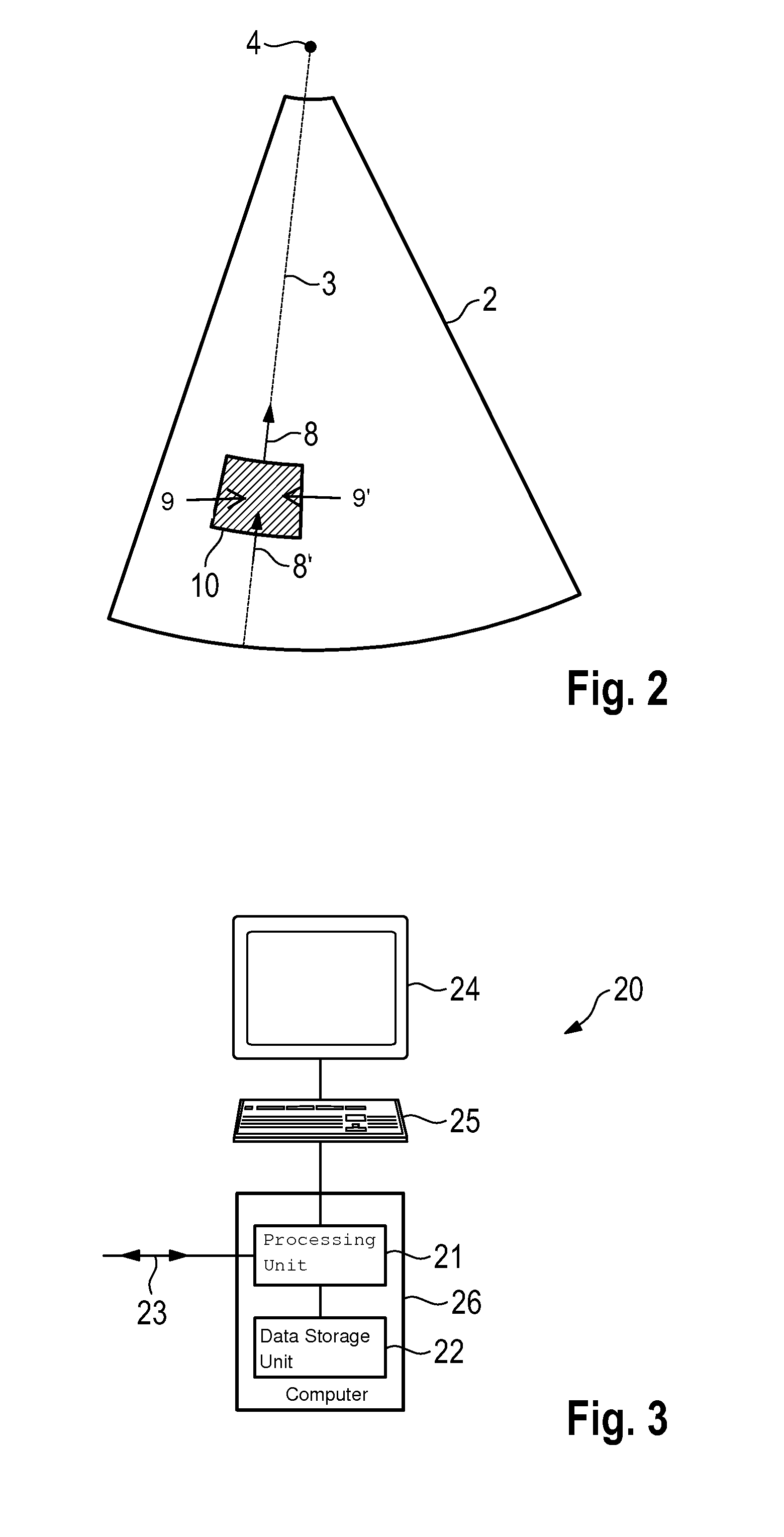
[0055]FIG. 2 shows the underlying concept of this calculation. The figure shows the same field-of-view 2 and a scan-line 3, as well as two Doppler velocities 8 and 8′. Further shown is a small region 10 at the boundaries of which the Doppler velocities 8 and 8′ have been measured. The mass balance in region 10 imposes that when ...


PUM


Abstract

A method and device for transforming a Doppler velocity dataset into a velocity vector field, the including: (a) providing a 2D or 3D Doppler velocity dataset, acquired by means of 2D or 3D ultrasonography from an object; b) calculating a velocity vector field by assuming the velocity at each point of the dataset to be the sum of the provided Doppler velocity and an additional vector field derived from an irrotational flow velocity, and by assuming the velocity vector field to be mathematically continuous, therefore solving an elliptical equation of the Poisson type.

Description

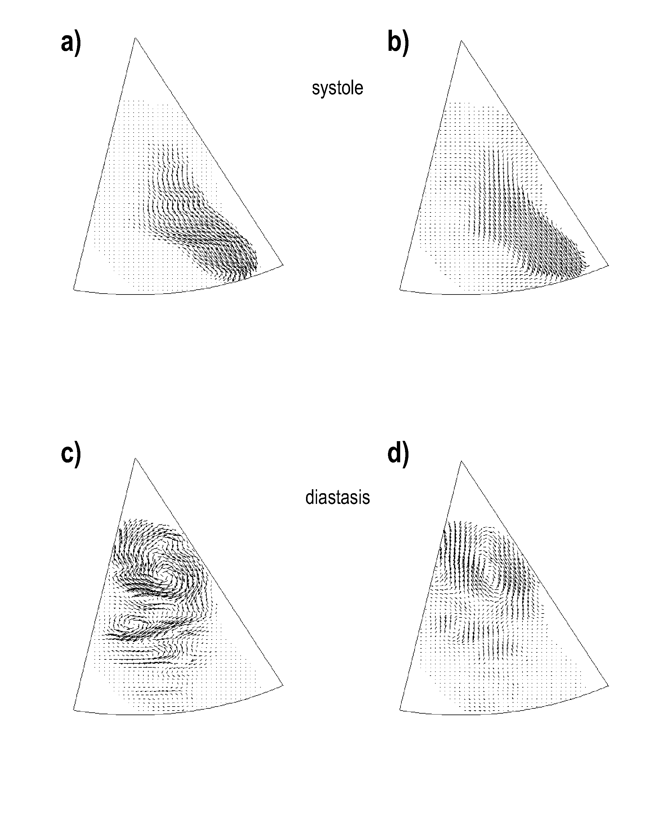
TECHNICAL FIELD[0001]The invention relates to a method for transforming a Doppler velocity dataset into a velocity vector field, and a computer program product, digital medium and device for performing said method.BRIEF DISCUSSION OF RELATED ART[0002]Blood in the heart and in circulation is expected to flow in a physiological appropriate manner. In presence of a modification, due to pathology or stress, blood immediately responds with a modification of its flow pattern. For example vortices are produced downstream of a stenosis, or stagnating intraventricular circulation is found next to a hypokinetic, ischemic, wall. The ability to evaluate the blood flow pattern would produce information to be used as an additional useful support to improve diagnostic and therapeutic processes. This would be particularly useful if such evaluation could be performed non-invasively.[0003]Non-invasive methods to evaluate blood flow based on MRI have been presented in literature (see Markl et al 2011 ...

Claims


Application Information

Patent Timeline
Patent Type & Authority Patents(United States)
IPC IPC(8): A61B8/00A61B8/06G01S15/89G06T11/20
CPCA61B8/06G01S15/8984G06T11/206G06T2207/10132G06T2207/30104
Inventor PEDRIZZETTI, GIANNITONTI, GIOVANNI
Owner TOMTEC IMAGING SYST
Learn More