
Container of wipes with dispensing nozzle

a technology of wipes and containers, applied in the direction of containers, pile separation, tray containers, etc., can solve the problems of wipes drying out, wipes being left in the tail of the next wipe, and the ‘stream’ of wipes being inadvertently extracted

Inactive Publication Date: 2014-10-14
GORDON MICHAEL JOHN
View PDF29 Cites 18 Cited by
  • Summary
  • Abstract
  • Description
  • Claims
  • Application Information

AI Technical Summary

Benefits of technology

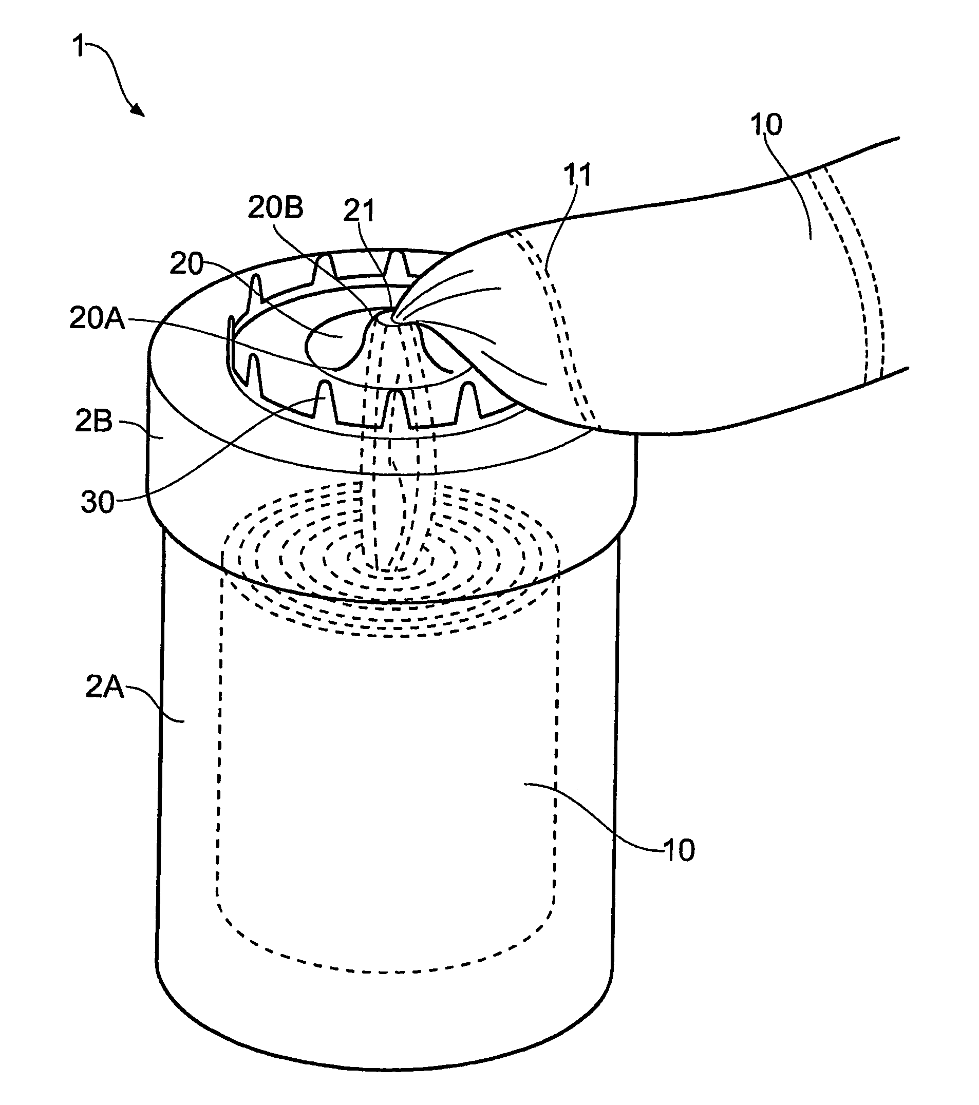
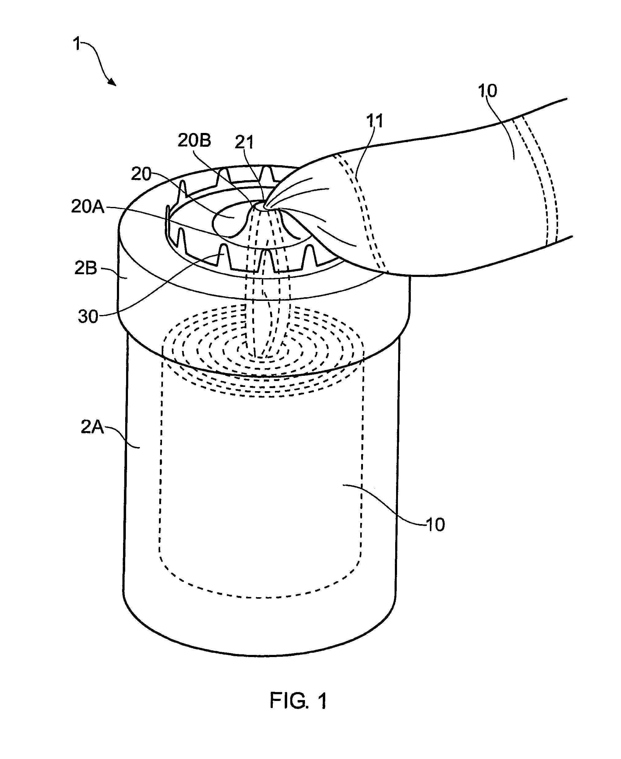
[0017]b) a dispensing nozzle extending from the housing, said nozzle being formed with a resilient aperture through which wipes can be withdrawn from the housing, said resilient aperture being biased towards a first contracted position and being expandable to a second expanded position as a wipe is extracted through the aperture to allow withdrawal of wipes therethrough, in use a wipe can be withdrawn through the nozzle and separated by rupturing the perforations joining the wipe to a next adjacent wipe with said nozzle expanding as required to allow passage of the wipe through the nozzle aperture, and said nozzle contracting around the tail of the next adjacent wipe to prevent release of moisture from the inside of the housing and to help prevent wicking of moisture from a wipe tail.
[0020]According to a third aspect of the invention there is provided a nozzle for use with the container, the nozzle comprising: a projection, which is adapted to flex toward a direction a wipe is being withdrawn, the projection being formed from a resiliently deformable material; has an aperture defined therein; and is biased into a contracted state, thereby maintaining the container substantially sealed, through which aperture, in use, a wipe passes, characterised in that, the material has a coefficient of static friction, such that a force applied to withdraw a towelette or wipe is sufficiently small as not to inadvertently tear towelettes or wipes at the onset of pulling; and the coefficient of dynamic friction is sufficiently large to exert a gripping force on the wipe, so as to apply a force of sufficient magnitude as to permit a towelette to pass through the aperture, promote the onset of tearing of the wipe along a preformed line of weakness and leave a tail of a subsequent wipe exposed.
[0022]Preferably therefore the nozzle is dimensioned such that any force pulling the wipe back through the aperture, into the housing, biases the nozzle aperture into a contracted state, thereby preventing premature rupture or tearing of the wipe and thus avoiding the need to re-thread a tail of a wipe through the aperture.
[0031]In a further embodiment the nozzle wall, so as to assist with insertion of a wipe, tapers in an inward direction from a widened base, and then curves outwards, into an annular projection defining an aperture inside the wall of the projection. As mentioned above the inside wall of the projection advantageously supports one or more ribs, gripping means or ratchet teeth to grip a wipe to help prevent a wipe passing back through the nozzle into the container.

Problems solved by technology

There are three main problems associated with such containers.
This results in the tail of the next wipe being left inside the container.
The result is that a user needs to remove the cap and feed the tail of the next wipe to be dispensed through the cap aperture.
Another problem has been that lines of perforations separating the wipes has occasionally fail to rupture as the wipe was removed resulting in a ‘stream’ of wipes being inadvertently extracted when only one was required.
A further problem was that wipes, which were intended to be moist, but if the container if wipes is stored and not used for a length of time, the wipes dry out due to wicking and because vapour can emerge from the container through the cap aperture.
However, it is not apparent how successful this device is at retaining moisture within the container, thereby ensuring that wipes, when dispensed are sufficiently wet.
The dispenser shown is relatively complex and comprises a significant number of discrete and relatively complex moulded items.
However, there still remains the problem, when withdrawing wipes from the container, that either perforations rupture before the wipe is fully withdrawn or lines of perforations separating the wipes fail to rupture, resulting in a ‘stream’ of wipes being dispensed.
On the one hand it is essential that the container remains as close to an hermetically sealed environment as possible, so as to ensure the wipes retain moisture; whereas on the other hand, too tight a grip on the wipes as they are being withdrawn, imparted by the dispensing orifice, either gives rise to unpredictable or premature tearing of the wipes.

Method used


Image

  • Container of wipes with dispensing nozzle
  • Container of wipes with dispensing nozzle
  • Container of wipes with dispensing nozzle

Examples


first embodiment

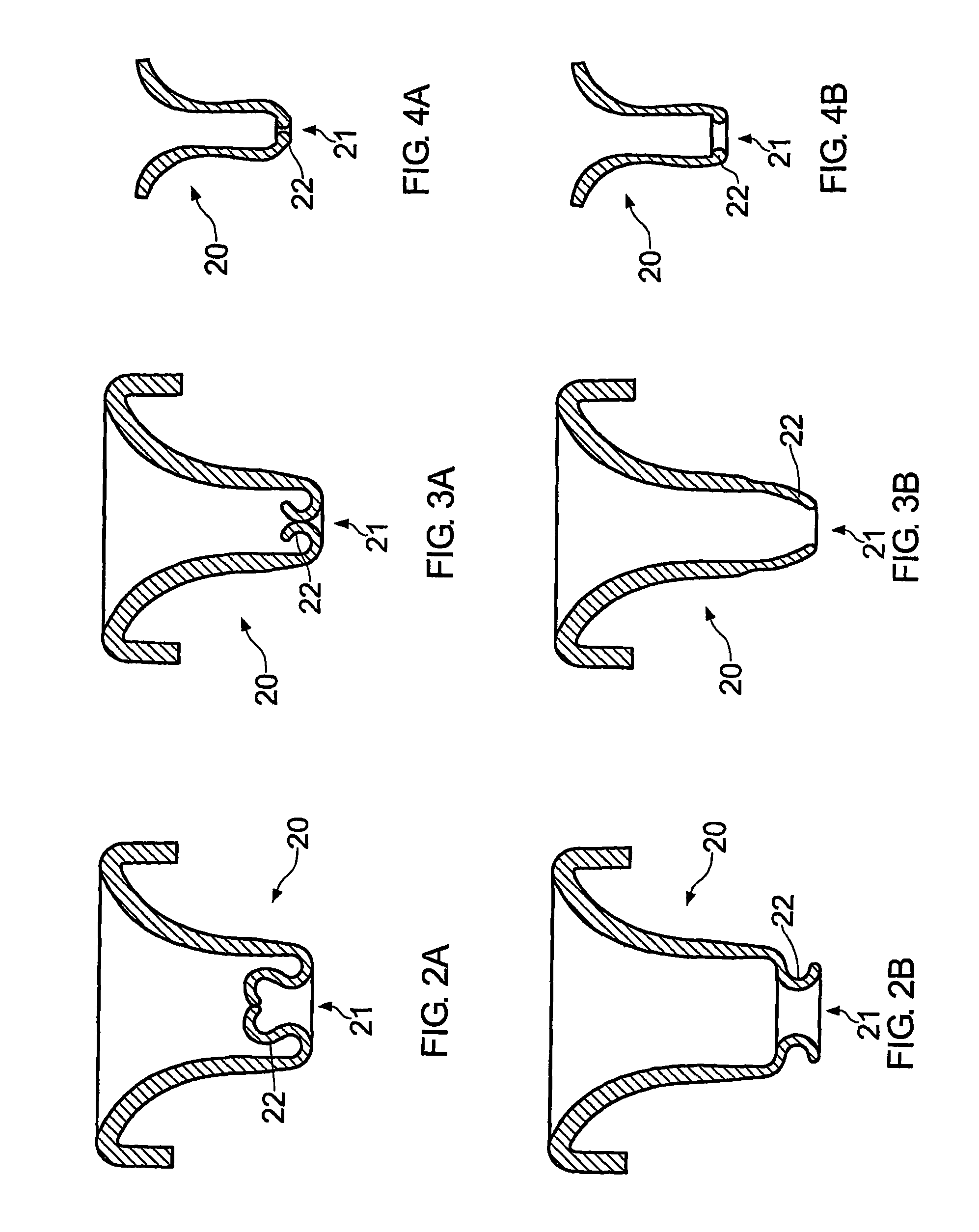
[0046]In FIGS. 2A and 2B there is shown in cross section nozzle 20 with an aperture 21 defined by a rolled ring 22 which moves from a first contracted position (FIG. 2A) to a second expanded position (FIG. 2B) as a wipe is extracted through the aperture. As shown, part of the nozzle adjacent the aperture inverts when moving from the first contracted position to the second expanded position. The nozzle 20 is shaped such that any force pulling a wipe back through the aperture when in the expanded state into the housing biases the nozzle aperture from its expanded state into a contract state.

[0047]In FIGS. 3A and 38 there is shown in cross section, a further embodiment of nozzle 20 with an aperture 21 defined by a rolled tip 22 which moves from a first contracted position (FIG. 3A) to a second expanded position (FIG. 3B) as a wipe is extracted through the aperture 21. As shown, part of the nozzle adjacent the aperture inverts when moving from the first contracted position to the second...

fourth embodiment

[0050]In FIGS. 5A and 5B there is shown in cross section nozzle 20 with an aperture 21 defined by an annular projection 22 which moves from a first contracted position (FIG. 5A) to a second expanded position (FIG. 5B) as a wipe is extracted through the aperture 21. Before a wipe is inserted therein, nozzle 20 wall has a widened base 20A which tapers inwards towards 20B and then curves outwards 20C into the annular projection 22. The tapering inwards and curving outwards of the wall creates a funnel to funnel a wipe through the aperture smoothly. This prevents wipes from bunching and clogging the nozzle, or premature severance of perforations before a wipe has fully exited the aperture 21 and exposed the tail of the next adjacent wipe.

[0051]The inside wall of the annular projection 22 may support one or more annular ratchet teeth 23 to grip a wipe to help prevent a wipe falling back through the nozzle 20 into a container. Instead of annular ratchet teeth, one or more annular ribs (e....


PUM

PropertyMeasurementUnit
forceaaaaaaaaaa
flexibleaaaaaaaaaa
coefficient of static frictionaaaaaaaaaa

Abstract

The invention relates to a container (1) of wipes with a dispensing nozzle (20). A housing (2A, 2B) is provided containing wipes (10). The wipes (10) formed on a continuous sheet of impregnated material with spaced lines of perforations (11) dividing the sheet of material into wipes. A dispensing nozzle (20) extends from the housing. The nozzle (20) is formed with a resilient aperture (21) through which wipes can be withdrawn from the housing. The resilient aperture (21) is expandable to allow withdrawal of (wipes 10) therethrough, but is biased towards a contracted state. In use a wipe can be withdrawn through the nozzle and separated by rupturing the perforations joining the wipe to a next adjacent wipe with the nozzle expanding as required to allow passage of the wipe through the nozzle aperture. The nozzle contracts around the tail of the next adjacent wipe to prevent release of moisture from the inside of the housing and to help prevent wicking of moisture from a wipe tail.

Description

CROSS REFERENCE TO RELATED APPLICATIONS[0001]This application is the US national phase of PCT application PCT / GB2007 / 003267, filed 29 Aug. 2007, published 5 Mar. 2008 as WO2008 / 025980, and claiming the priority of British patent application 0617067.7 itself filed 29 Aug. 2006 and British patent application 0710596.8 itself filed 4 Jun. 2007, whose entire disclosures are herewith incorporated by reference.FIELD OF THE INVENTION[0002]The present invention relates to a container of wipes with a dispensing nozzle.BACKGROUND OF INVENTION[0003]It is well known to house wipes in containers. Such containers typically comprise a cylindrical housing with a sealed end and an open end. Wipes are stored in the housing. An end cap is typically provided for the open end, which seals the container ideally in an hermetically sealed environment. An aperture is also provided in the end cap through which wipes are dispensed and which is usually located in a recess which receives the end cap.[0004]Wipes...

Claims


Application Information

Patent Timeline
Patent Type & Authority Patents(United States)
IPC IPC(8): A47K10/32
CPCA47K10/3818B65D83/0805A47K10/38A47K10/3827
Inventor GORDON, MICHAEL JOHN
Owner GORDON MICHAEL JOHN
Learn More