Method and system for creating an illusion of a skylight

Active Publication Date: 2014-10-07
THE SKY FACTORY LC
View PDF7 Cites 3 Cited by
  • Summary
  • Abstract
  • Description
  • Claims
  • Application Information

AI Technical Summary

Benefits of technology

The present invention improves the realism of the illumination of a panel by eliminating shadows cast by the T-bar. It provides the illusion of a casement-type window frame and allows for the easy and cost-efficient implementation of a trompe-l'oeil skylight in a hung ceiling system. The invention also includes a unified recessed trompe-l'oeil skylight with a non-rectangular shape and a rectangular shaped flush intermediate plate extending to the skylight. Additionally, the invention provides a skylight without an internal grid system.

Problems solved by technology

While this is often very effective at helping to pacify a nervous patient, it is often not practical, especially in interior spaces without roof exposure or in shielded spaces used for radiological imaging or diagnostic equipment which often is required to be in completely enclosed and controlled areas.
While they do tend to create a more pleasant environment, they often fail to trick the eye into believing it is a real skylight, and they often exhibit unwanted shadows created by the T-bar in the hung ceiling grid.
In the past it has been difficult to make a trompe-l'oeil skylight which has a shape which is generally non-rectangular.

Method used


Image

  • Method and system for creating an illusion of a skylight
  • Method and system for creating an illusion of a skylight
  • Method and system for creating an illusion of a skylight

Examples


Embodiment Construction

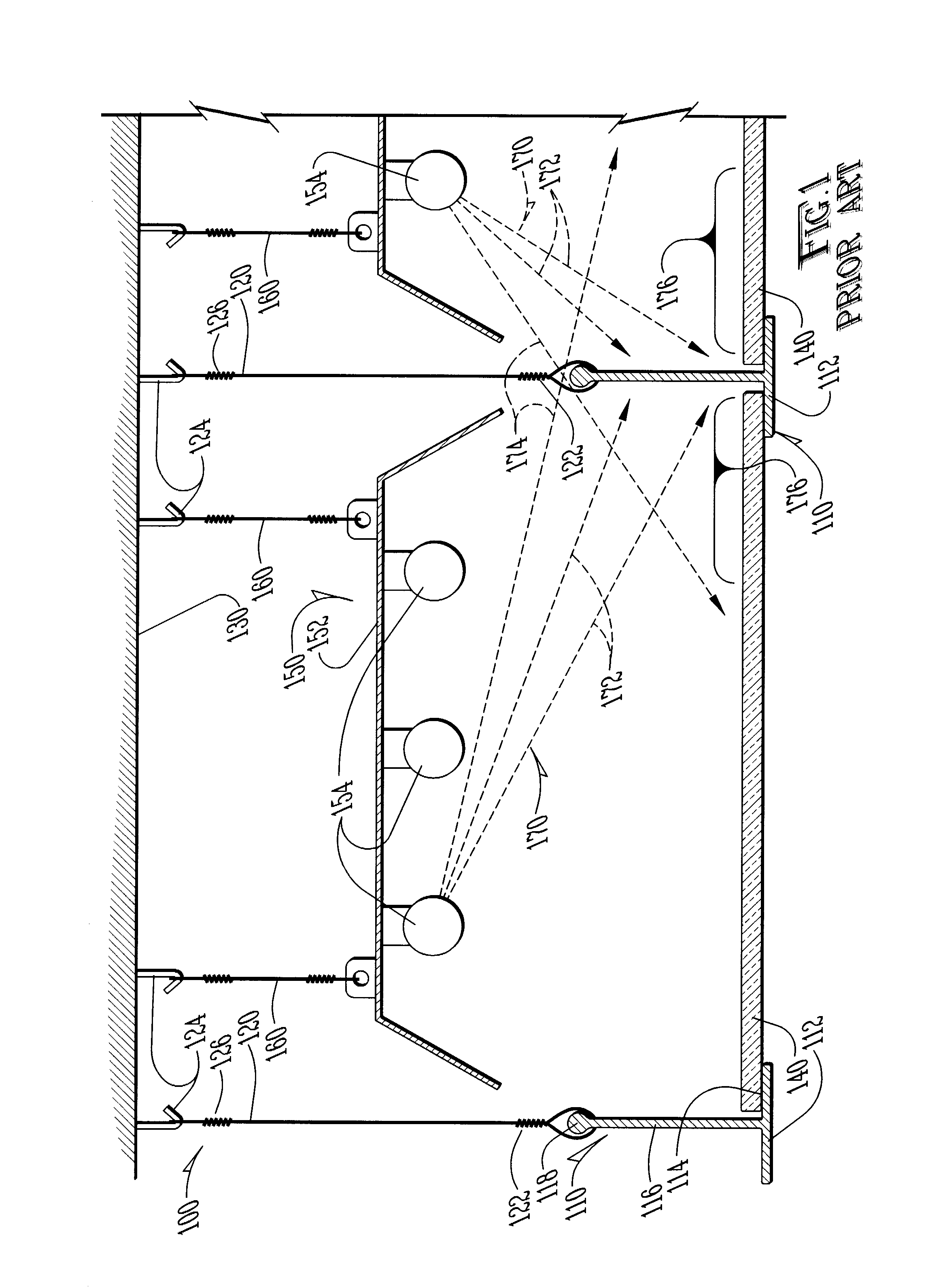
[0028]Now referring to the drawings wherein like numerals refer to like matter throughout, and more specifically referring to FIG. 1, there is shown a side view of a hung ceiling system of the prior art generally designated 100 which includes a translucent sky image panel 140. This end view or cross-sectional view is of a translucent sky image panel disposed with a T-bar grid member 110 on each side. The T-bar grid member 110 is a long linear T-shaped element which has a T-bar grid member bottom surface 112 which is visible to the consumer along with other translucent sky image panels 140 and other ceiling tiles (not shown). T-bar grid member 110 has a T-bar grid member bottom shelf 114 where the translucent sky image panel 140 or a regular ceiling tile would rest. T-bar grid member 110 has a T-bar grid member vertical member 116 and a T-bar grid member top portion 118 which is coupled to a T-bar suspension wire 120 by a T-bar suspension wire bottom winding 122. T-bar suspension wir...


PUM


Abstract

A system and method for creating a trompe-l'oeil skylight in a ceiling where a light emitting image of the sky is provided in a structure configured to emulate a skylight frame, including an embodiment of a unified non-rectangular sky image area in a substantially rectangular fixture which mount as a single unit into a substantially rectangular hole in a ceiling.

Description

CROSS-REFERENCE TO RELATED APPLICATION[0001]This application is a continuation-in-part from an application filed on Dec. 23, 2008, with an application Ser. No. 12 / 342,833, now U.S. Pat. No. 7,959,316; which is a continuation of application Ser. No. 10 / 908,940 filed on Jun. 1, 2005, now U.S. Pat. No. 7,481,550, by the same inventors, with the same title as the within application.FIELD OF THE INVENTION[0002]The present invention generally relates to methods and systems for creating an illusion of a skylight.BACKGROUND OF THE INVENTION[0003]In recent years, medical professionals have used various types of methods to calm a patient who is undergoing or waiting for an important medical procedure. One example is the use of a skylight so the patient can have a view of the outdoors. While this is often very effective at helping to pacify a nervous patient, it is often not practical, especially in interior spaces without roof exposure or in shielded spaces used for radiological imaging or di...

Claims


Application Information

Patent Timeline
IPC IPC(8): F21S8/00
CPCF21W2121/00F21W2131/205E04B9/32F21S8/04Y10S362/812F21W2121/008Y10S362/806F21V3/00E04B9/006F21S8/061F21V21/049E04B9/242F21S8/026F21Y2113/00F21V33/006
Inventor SCHREIBER, RADIMWITHERSPOON, SKYE
Owner THE SKY FACTORY LC
Why Eureka
Try Eureka