
SMPS having a safety arrangement, a method of operating a SMPS, and a controller therefor

a safety arrangement and power supply technology, applied in the direction of electric variable regulation, process and machine control, instruments, etc., can solve the problems of power supply being disabled, unable to discharge the charge of the capacitor, and the user remains at risk of electrical shock, etc., to achieve easy control and dissipate energy in the resistive load

Active Publication Date: 2014-09-30
NXP BV
View PDF13 Cites 15 Cited by
  • Summary
  • Abstract
  • Description
  • Claims
  • Application Information

AI Technical Summary

Benefits of technology

The patent describes a safety circuit for a detector and switch that can be used to discharge the input capacitor of a power factor correction stage when the mains supply is disconnected or unplugged. This circuit prevents power dissipation during normal operation and is designed to improve energy efficiency and cooler operation. The circuit can use a bus capacitor or a current source to discharge the input capacitor and can be easily integrated into existing circuit configurations. The technical effects of this patent include improved safety, reduced energy wasted, and more compact and cost-effective overall converters.

Problems solved by technology

Otherwise, there remains a risk of electrical shock to the user, by inadvertently contacting the terminals of the plug.
If the power supply is operating and fully loaded, the load will in most instances rapidly result in the discharge of the charge on the capacitors.
However, under no-load conditions, the power supply may have been disabled; also, under conditions where the mains voltage has fallen below acceptable levels, (so-called “brownout” conditions), the power supply may have been switched off.
Existing resistive discharge solutions suffer the disadvantage that the resistors dissipate power.
Although this power dissipation, which for a typical application may be between 20 and 100 mW, is insignificant under most fully loaded conditions, under conditions of no-load, it is relatively appreciable.

Method used


Image

  • SMPS having a safety arrangement, a method of operating a SMPS, and a controller therefor
  • SMPS having a safety arrangement, a method of operating a SMPS, and a controller therefor
  • SMPS having a safety arrangement, a method of operating a SMPS, and a controller therefor

Examples


Embodiment Construction

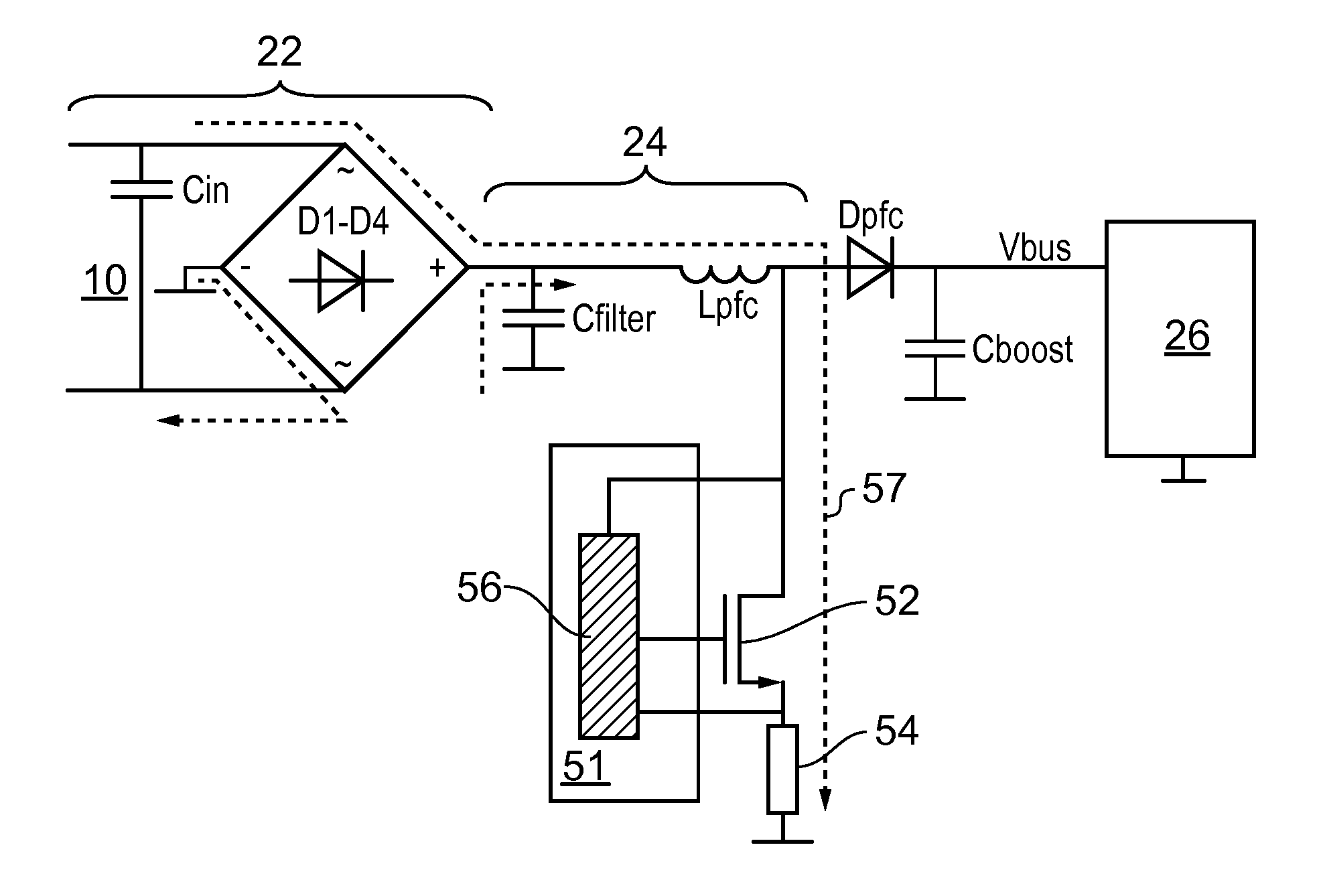
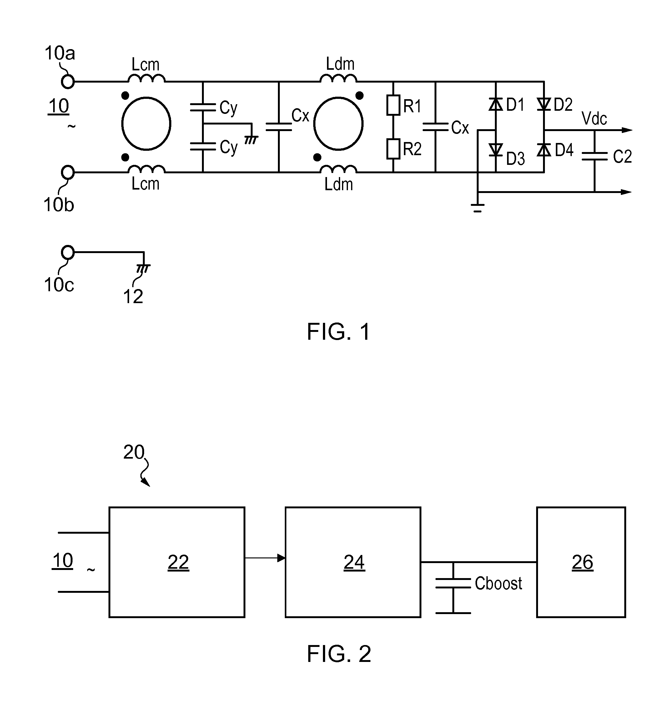
[0044]FIG. 1 shows a circuit diagram of an input filter and rectifier; the circuit has an input 10, having live and neutral terminals 10a and 10b, for connection to a mains voltage together with a protective earth terminal 10c for connection to a protective earth 12, and has a common mode inductance Lcm. In this exemplary input filter, there is a pair of Y capacitors (Y-Caps) Cy connected between a secondary ground (that is to say, to a ground on the output, or secondary, side of the SMPS) and the respective mains terminals 10a and 10b. The input filter is shown as having two X capacitors (X-Caps) Cx, connected to the input terminals 10a and 10b, one either side of the differential mode inductance Ldm. The input filter shown further has a pair of series-connected resistors R1 and R2 connected across the input terminals. The input filter described above is connected to a full-bridge rectifier comprising diodes D1-D4, the output of which is connected to the next stage, and has smoothi...


PUM


Abstract

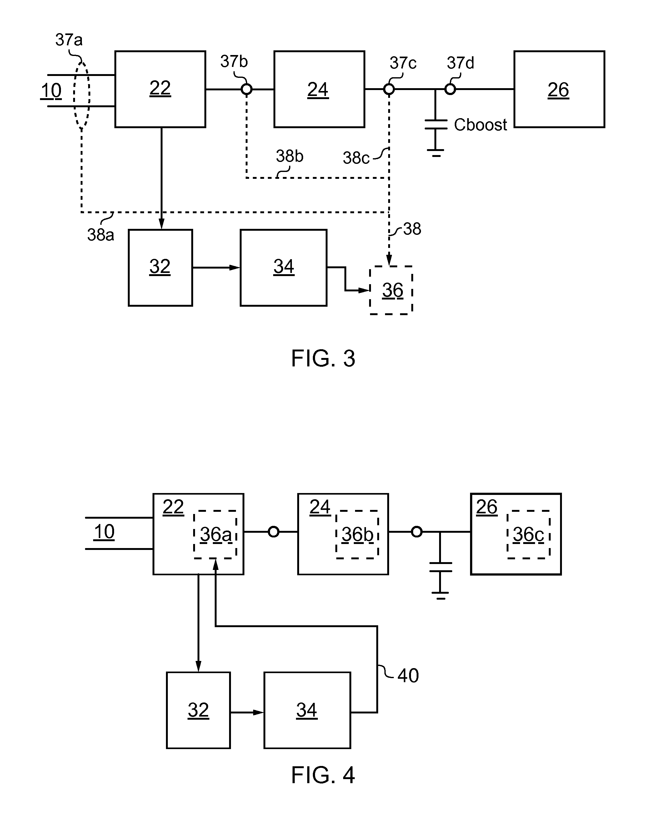
A switched mode power supply (SMPS) is disclosed. The SMPS includes a mechanism for discharging charge stored in an input capacitor, upon the SMPS becoming disconnection from the mains, for instance by being unplugged. The SMPS includes a detector for detecting the disconnection of the mains, and a discharge circuit. The discharge circuit comprises a discharge element. The discharge element may be a part of the SMPS which is used otherwise, for instance, a high-voltage current source, or a bus capacitor or it may be an additional element, for instance a resistance load. The discharge circuit is adapted for, in response to the detector detecting a disconnection of the mains, discharging the input capacitor along a path. The detector controls a switch which engages the discharge circuit upon the detection. The switch forms a part of the discharge path.

Description

CROSS-REFERENCE TO RELATED APPLICATIONS[0001]This application claims the priority under 35 U.S.C. §119 of European patent application no. 10162788.3, filed on May 13, 2010, the contents of which are incorporated by reference herein.FIELD OF THE INVENTION[0002]This invention relates to switched mode power supplies, to controllers therefor and to methods of operating the same.BACKGROUND OF THE INVENTION[0003]In order to suppress electromagnetic interference (EMI), in most cases an input filter is required on the input side of switched mode power supplies (SMPS). In addition to an inductance, EMI filters typically include one or more capacitors connected between the mains terminals. These capacitors are also known as XCaps. EMI filters typically also include one or more capacitances connected between one of the mains terminals and a protective Earth (which are also known as YCaps). Typically, this protective Earth takes the form of a secondary ground, to which the Y-Caps are connected,...

Claims


Application Information

Patent Timeline
Patent Type & Authority Patents(United States)
IPC IPC(8): H02M1/00H02M3/155
CPCH02M3/155H02M1/322
Inventor HALBERSTADT, HANS
Owner NXP BV
Learn More