
Method and apparatus for automated placement of scanned laser capsulorhexis incisions

a technology of capsulorhexis and laser capsulorhexis, which is applied in the field of ophthalmic surgical procedures and systems, can solve the problems of difficult mechanical rupture, inability of surgeons to adequately visualize the capsule, and difficulty in implantation of intraocular lenses. to achieve the effect of facilitating the implantation of intraocular lenses

Active Publication Date: 2014-09-30
AMO DEVMENT
View PDF23 Cites 58 Cited by
  • Summary
  • Abstract
  • Description
  • Claims
  • Application Information

AI Technical Summary

Benefits of technology

The techniques and systems described in this patent make it easier to prepare for the implantation of intraocular lenses (IOLs) by using image guidance to align a capsulorhexis incision. This incision can be any shape that allows for the placement of advanced IOL devices or fixed accommodating IOLs. Overall, this patent provides a better way to prepare for and perform eye surgery with IOLs.

Problems solved by technology

Using the older technique of can-opener capsulotomy, or even with the continuous capsulorhexis, problems may develop related to inability of the surgeon to adequately visualize the capsule due to lack of red reflex, to grasp it with sufficient security, to tear a smooth circular opening of the appropriate size without radial rips and extensions or technical difficulties related to maintenance of the anterior chamber depth after initial opening, small size of the pupil, or the absence of a red reflex due to the lens opacity.
However, visualization of the capsule is but one issue.
The orientation of the eye can also cause problems for the surgeon, as the capsulorhexis incision may be made off-center if parallax error is introduced by the stereoscopic imaging system.
Additional complications arise in patients with weak zonules (typically older patients) and very young children that have very soft and elastic capsules, which are very difficult to mechanically rupture.

Method used


Image

  • Method and apparatus for automated placement of scanned laser capsulorhexis incisions
  • Method and apparatus for automated placement of scanned laser capsulorhexis incisions
  • Method and apparatus for automated placement of scanned laser capsulorhexis incisions

Examples


Embodiment Construction

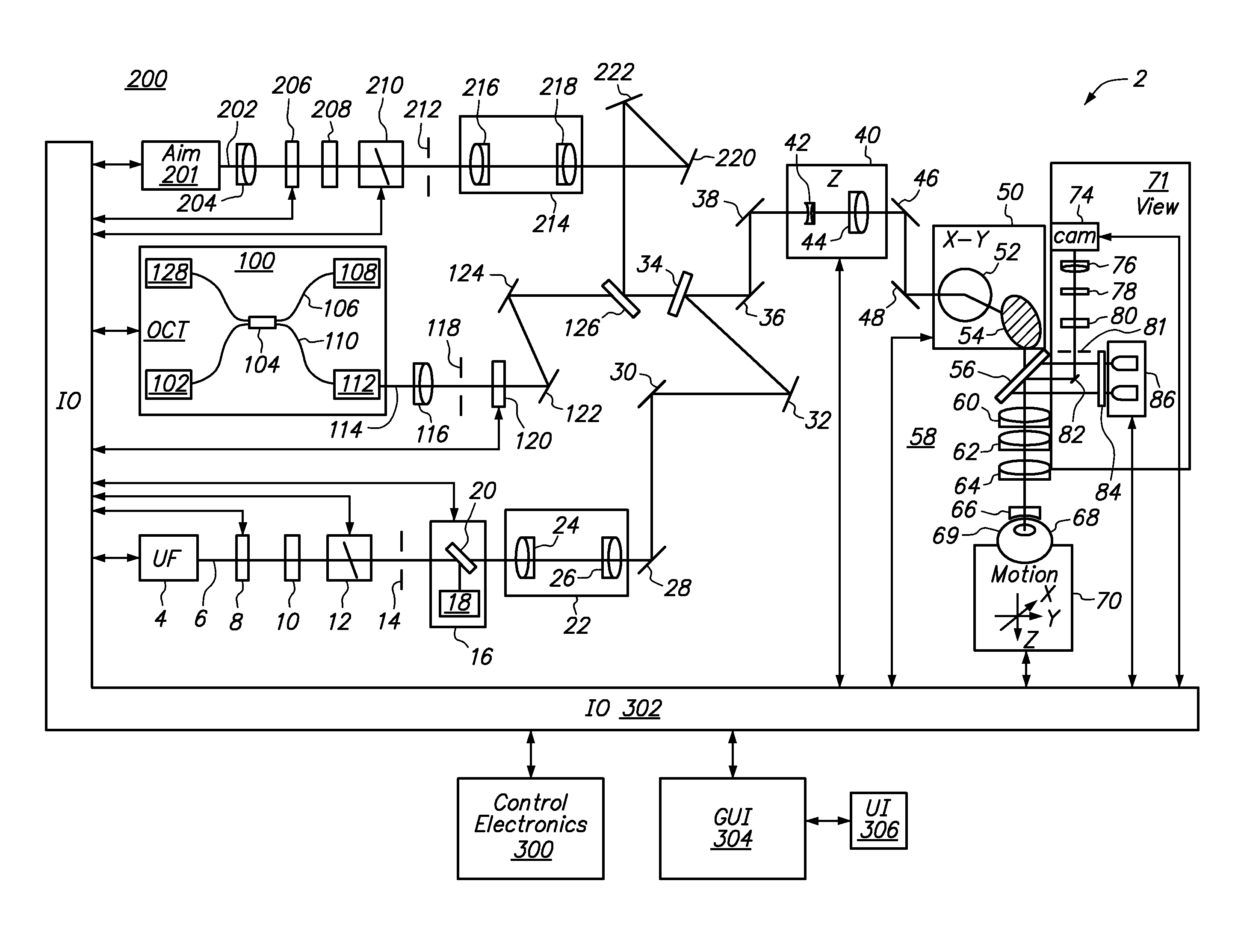
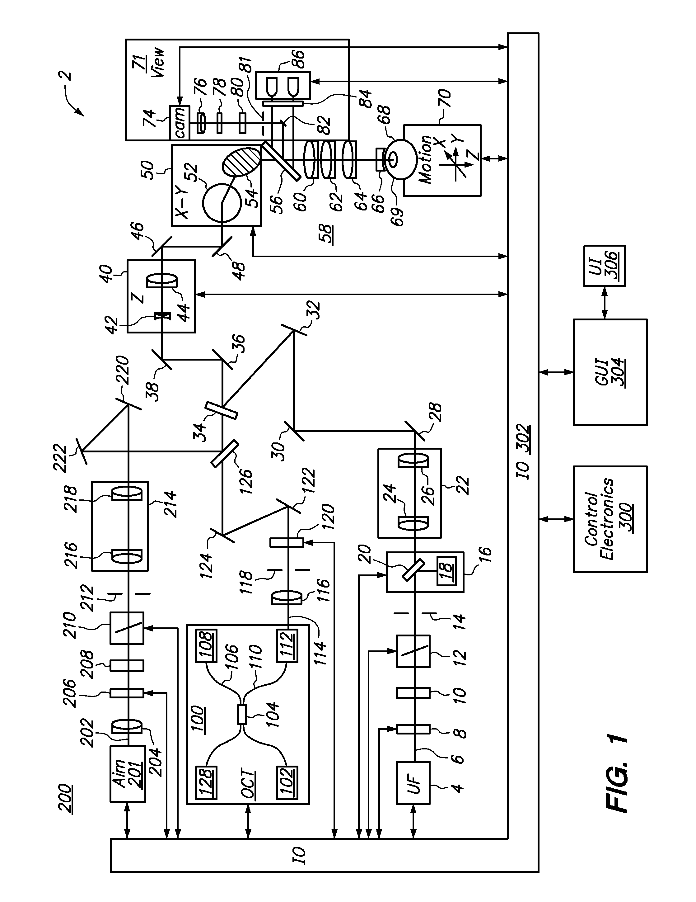
[0035]The present invention can be implemented by a system that projects or scans an optical beam into a patient's eye 68, such as system 2 shown in FIG. 1 which includes an ultrafast (UF) light source 4 (e.g. a femtosecond laser). Using this system, a beam may be scanned in a patient's eye in three dimensions: X, Y, Z. In this embodiment, the UF wavelength can vary between 1010 nm to 1100 nm and the pulse width can vary from 100 fs to 10000 fs. The pulse repetition frequency can also vary from 10 kHz to 250 kHz. Safety limits with regard to unintended damage to non-targeted tissue bound the upper limit with regard to repetition rate and pulse energy; while threshold energy, time to complete the procedure and stability bound the lower limit for pulse energy and repetition rate. The peak power of the focused spot in the eye 68 and specifically within the crystalline lens 69 and anterior capsule of the eye is sufficient to produce optical breakdown and initiate a plasma-mediated ablat...


PUM


Abstract

Systems and methods are described for cataract intervention. In one embodiment a system comprises a laser source configured to produce a treatment beam comprising a plurality of laser pulses; an integrated optical system comprising an imaging assembly operatively coupled to a treatment laser delivery assembly such that they share at least one common optical element, the integrated optical system being configured to acquire image information pertinent to one or more targeted tissue structures and direct the treatment beam in a 3-dimensional pattern to cause breakdown in at least one of the targeted tissue structures; and a controller operatively coupled to the laser source and integrated optical system, and configured to adjust the laser beam and treatment pattern based upon the image information, and distinguish two or more anatomical structures of the eye based at least in part upon a robust least squares fit analysis of the image information.

Description

RELATED APPLICATION DATA[0001]The present application claims the benefit under 35 U.S.C. §119 to U.S. provisional patent application Ser. No. 61 / 297,624 filed Jan. 22, 2010. The foregoing application is hereby incorporated by reference into the present application in its entirety.FIELD OF THE INVENTION[0002]The present invention relates to ophthalmic surgical procedures and systems.BACKGROUND OF THE INVENTION[0003]Intraocular lens implantation is one of the most commonly performed surgical procedures in the world with an estimated 14 million cases annually performed worldwide.[0004]Modern surgery is typically performed using a technique termed phacoemulsification in which an ultrasonic tip with an associated water stream for cooling purposes is used to sculpt the relatively hard nucleus of the lens after performance of an opening in the anterior lens capsule termed anterior capsulotomy or more recently capsulorhexis. Following these steps as well as removal of residual softer lens c...

Claims


Application Information

Patent Timeline
Patent Type & Authority Patents(United States)
IPC IPC(8): A61F9/08A61F9/008A61B3/107
CPCA61F9/008A61B3/107A61F2009/00851A61B5/0066A61F9/00825G06T7/0085G06T2207/30041A61F2009/00889G06T7/0012A61F2009/0087G06T7/602G06T7/13G06T7/149A61B3/102A61B3/145A61F9/0084A61F9/009A61F2009/00865A61F2009/00872A61F2009/00876A61F2009/00897G06T2207/10101
Inventor ANGELEY, DAVID G.GOODING, PHILLIPWOODLEY, BRUCE R.MARCELLINO, GEORGE
Owner AMO DEVMENT
Learn More