Mobile chair

Active Publication Date: 2014-09-30
WHITESIDE MFG
View PDF78 Cites 19 Cited by
  • Summary
  • Abstract
  • Description
  • Claims
  • Application Information

AI Technical Summary

Benefits of technology

The aim of this patent is to make a mobile chair that is stronger and more stable. The attachment of the seat to the lower frame helps to achieve this.

Problems solved by technology

At least some of these units lack the stability required in the environment which finds the mechanic.
However, such trays detrimentally affect the maneuverability of the chairs which is controlled by the legs and feet of the mechanic.
In either of those positions, it is not easy to maneuver the chair especially without having the tray engage the legs of the user.

Method used


Image

  • Mobile chair
  • Mobile chair
  • Mobile chair

Examples


Embodiment Construction

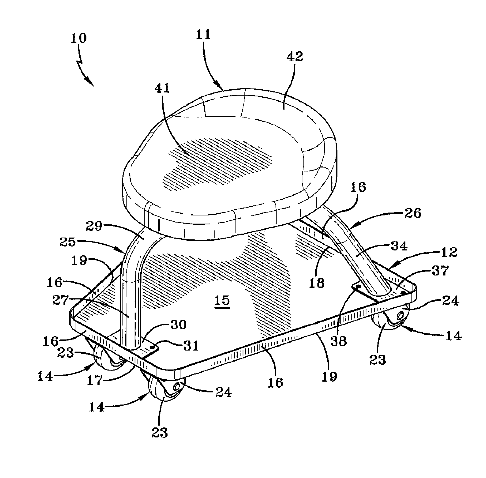
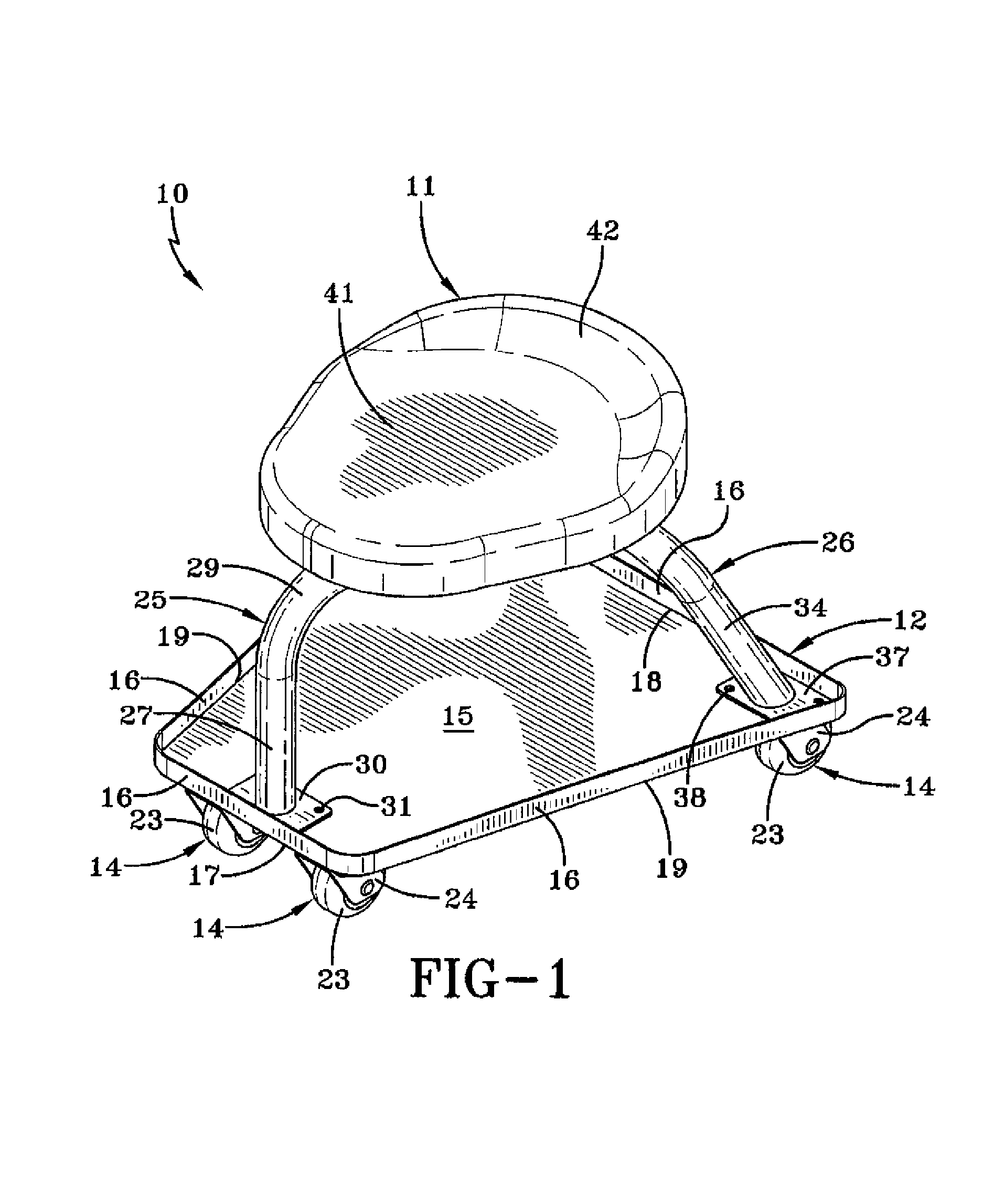
[0018]A mobile chair may in accordance with the present invention is generally indicated by the numeral 10. Chair 10 includes a seat portion generally indicated by the numeral 11, a tray generally indicated by the numeral 12, a support brace assembly generally indicated by the numeral 13, and a plurality of caster assemblies generally indicated by the numeral 14.

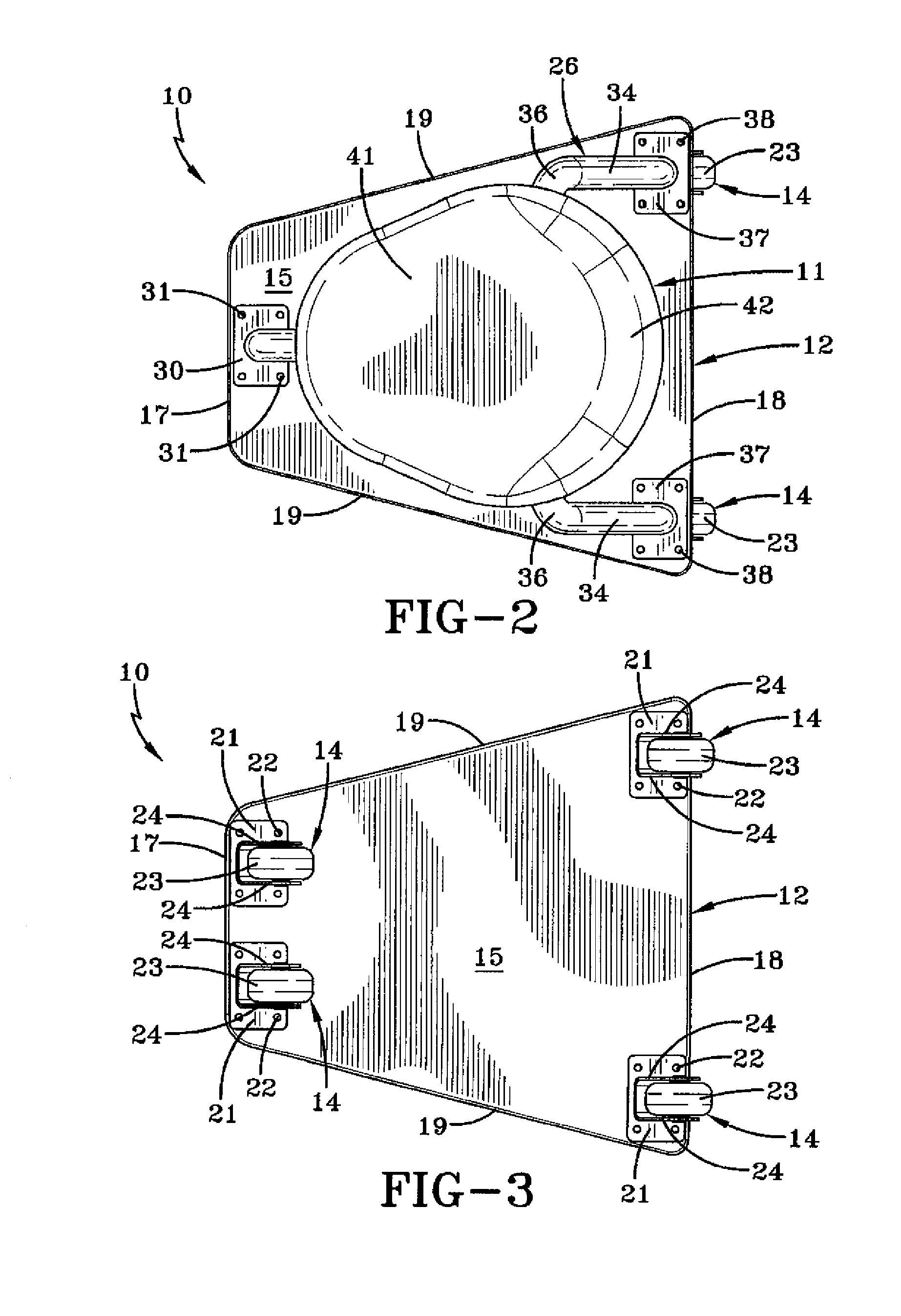
[0019]Tray 12 includes a generally horizontal, flat surface 15 which has a flange 16 extending upwardly around its periphery. As such, items can be placed on surface 15 and are confined thereon by flange 16 for ready access to the user of chair 10. Tray 12 and surface 15 are generally trapezoidal in configuration having opposed, generally parallel front and rear edges, 17 and 18 respectively, and opposed side edges 19 which converge toward each other from rear edge 18 to front edge 17. Thus, front edge 17 is shorter in length than rear edge 18. Tray surface 15 is provided with a plurality of holes 20, not all of which are sh...


PUM


Abstract

A mobile chair (10) includes a seat (11), and a tray (12) having a front edge (17) that is shorter than its rear edge (18). A caster assembly (14) is carried by the tray (12) at the front and rear corners of the tray (12). A brace assembly (13) attaches the seat (11) to the tray (12) and includes a tube portion (27) attached to the tray (12) between the caster assemblies (14) at the front corners of the tray (12) and tube portions (34) attached to the tray (12) near the rear corners.

Description

TECHNICAL FIELD[0001]This invention relates to a mobile chair of the type often used by mechanics. More particularly, this invention relates to such a chair having improved stability and maneuverability.BACKGROUND ART[0002]There are a wide variety of designs of known mobile chairs such as those used by mechanics to maneuver themselves around while working on portions of vehicles. Typically, these chairs include a lower frame which carries casters, a seat portion, and one or more curved braces which attach the frame to the seat portion. Alternatively, legs could extend from the corners of the seat portion to the corners of the frame. At least some of these units lack the stability required in the environment which finds the mechanic.[0003]The frame of such chairs also typically carries a tray to receive and hold a plurality of tools used by the mechanic. These trays are rectangular in nature and are positioned under the seat. They also extend forward of the seat for ease of access by...

Claims


Application Information

Patent Timeline
IPC IPC(8): B25H5/00
CPCB25H5/00
Inventor WHITESIDE, KIRT E.OBITTS, SHANESCHENK, BRADEN C.
Owner WHITESIDE MFG
Why Eureka
Try Eureka