
Systems and methods for cargo scanning and radiotherapy using a traveling wave linear accelerator based x-ray source using current to modulate pulse-to-pulse dosage

a linear accelerator and x-ray source technology, applied in the direction of wave/particle radiation, material analysis, instruments, etc., can solve the problems of false positives, incorrect identification of z-number of scanned material, unstable beam energy of linear accelerator,

Active Publication Date: 2014-09-16
ACCURAY
View PDF49 Cites 4 Cited by
  • Summary
  • Abstract
  • Description
  • Claims
  • Application Information

AI Technical Summary

Benefits of technology

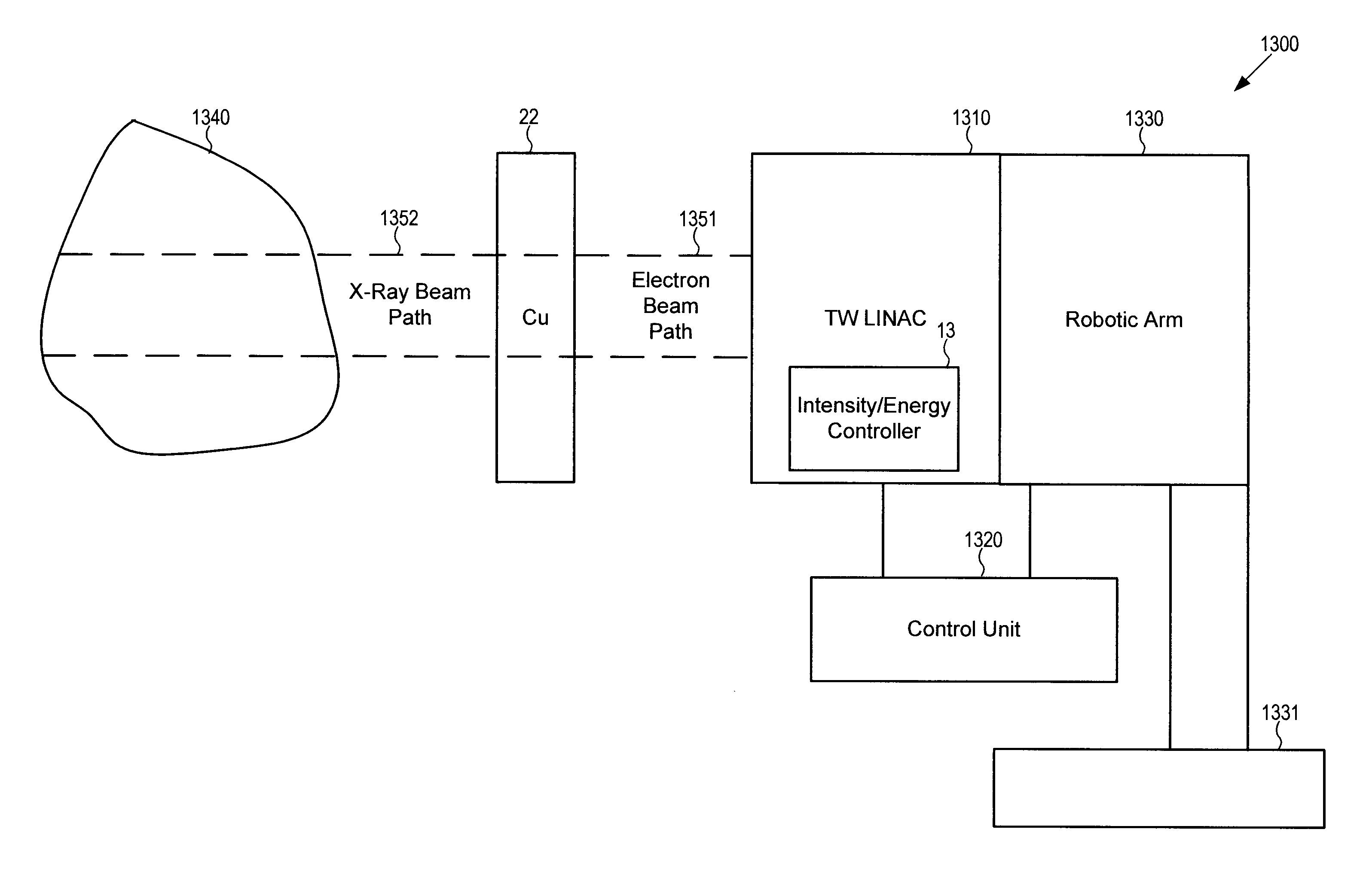
[0017]The traveling wave linear accelerator may also include a control unit operatively associated with the robotic arm and with the intensity controller. The control unit may be configured to send a first intensity / energy adjustment command to cause the intensity controller to determine a first electron beam current, a first RF power factor, and a first frequency adjustment factor to provide a first output dose rate and a first energy of a first set of electrons, as well as a first position command to the robotic arm to cause the robotic arm to adjust the angle to irradiate a first portion of the tumor volume with x-rays generated by the first set of electrons. The control unit further may be configured to send a second intensity / energy adjustment command to cause the intensity controller to determine a second electron beam current, a second RF power factor, and a second frequency adjustment factor to provide a second output dose rate and a second energy of a second set of electrons; as well as to send a second position command to the robotic arm to cause the robotic arm to adjust the angle to irradiate a second portion of the tumor volume with x-rays generated by the second set of electrons.
[0021]In embodiments where the traveling wave linear accelerator is used for radiotherapy applications, the method may include sending a first intensity / energy adjustment command to cause the intensity controller to determine a first electron beam current, a first RF power factor, and a first frequency adjustment factor to provide a first output dose rate and a first energy of a first set of electrons; and sending a first position command to a robotic arm on which the linear accelerator and an x-ray target are mounted to cause the robotic arm to adjust an angle to irradiate a first portion of a tumor volume with x-rays generated by the first set of electrons. The method also may include sending a second intensity / energy adjustment command to cause the intensity controller to determine a second electron beam current, a second RF power factor, and a second frequency adjustment factor to provide a second output dose rate and a second energy of a second set of electrons; and sending a second position command to the robotic arm to cause the robotic arm to adjust the angle to irradiate a second portion of the tumor volume with x-rays generated by the second set of electrons.

Problems solved by technology

However, conventional dual energy x-ray inspection systems use a standing wave LINAC that is vulnerable to frequency and power jitter and temperature fluctuations, causing the beam energy from the linear accelerator to be unstable when operated to accelerate electrons to a low energy.
The energy jitter and fluctuations can create image artifacts, which cause an improper Z number of a scanned material to be identified.
This can cause false positives (in which a targeted material is identified even though no targeted material is present) and false negatives (in which a targeted material is not identified even though targeted material is present).

Method used


Image

  • Systems and methods for cargo scanning and radiotherapy using a traveling wave linear accelerator based x-ray source using current to modulate pulse-to-pulse dosage
  • Systems and methods for cargo scanning and radiotherapy using a traveling wave linear accelerator based x-ray source using current to modulate pulse-to-pulse dosage
  • Systems and methods for cargo scanning and radiotherapy using a traveling wave linear accelerator based x-ray source using current to modulate pulse-to-pulse dosage

Examples


Embodiment Construction

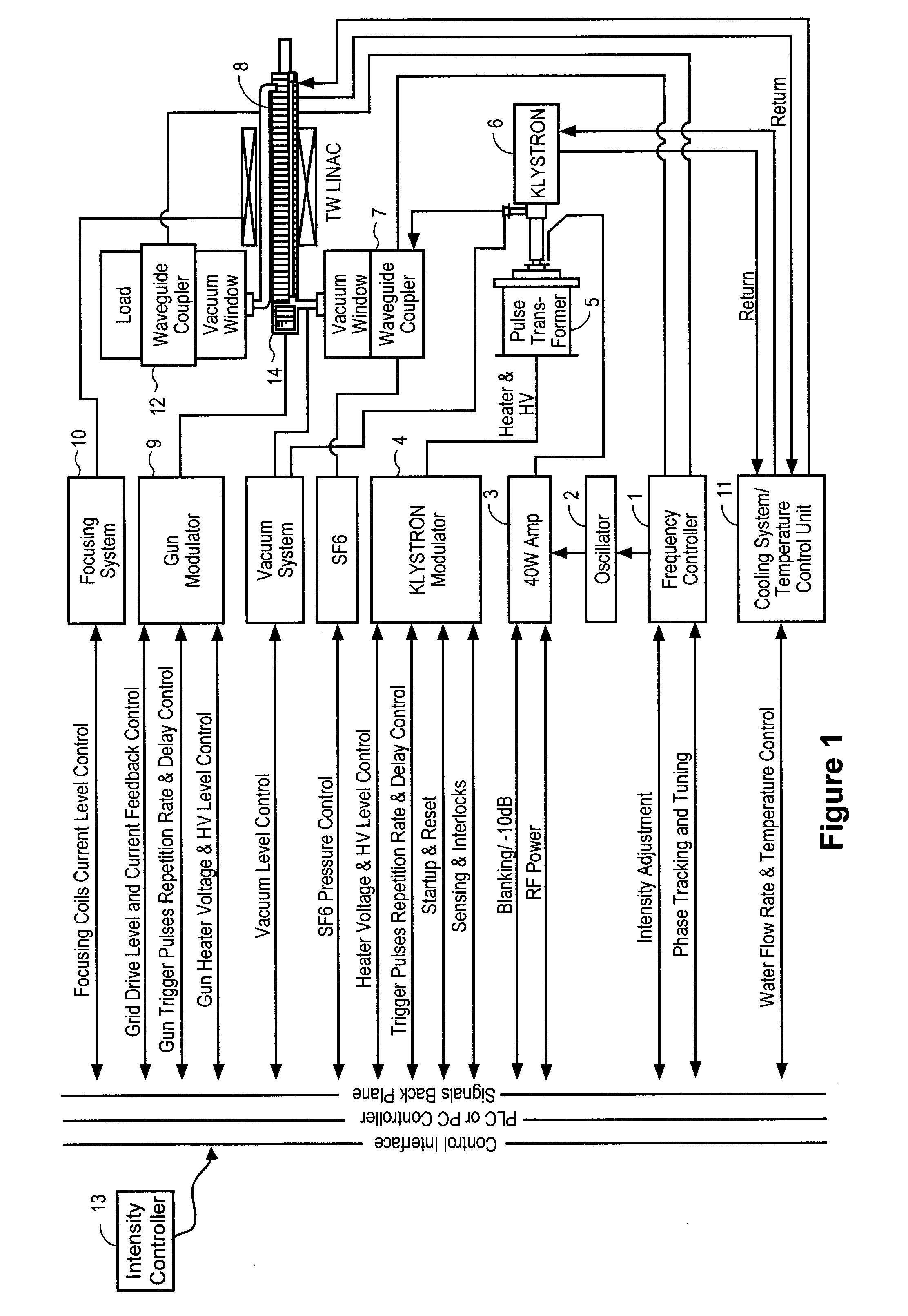
[0037]The present disclosure relates to systems and methods for use in generating x-rays with modulated pulse-to-pulse dosage, i.e., intensity, using a traveling wave linear accelerator (TW LINAC), particularly for use in cargo scanning and radiotherapy applications.

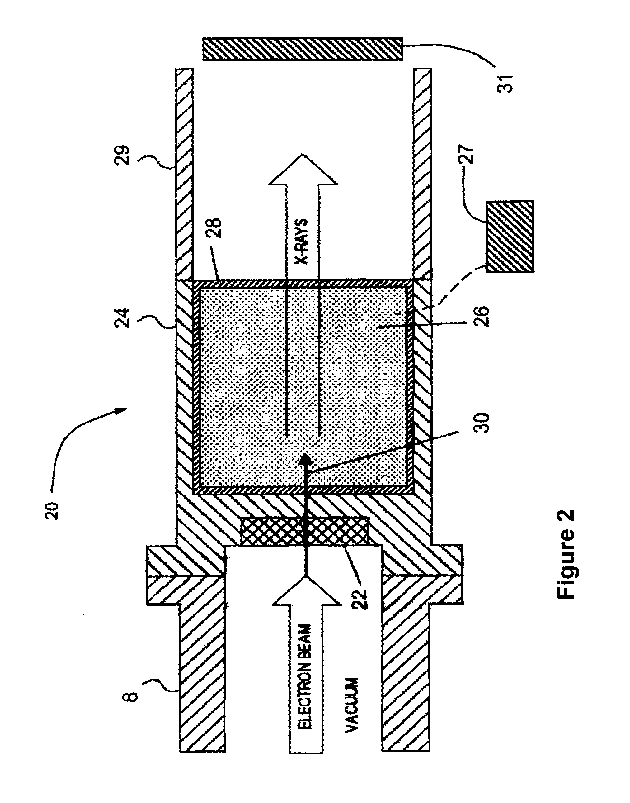
[0038]In an exemplary TW LINAC, electrons injected into an accelerator structure of the TW LINAC by an electron gun are accelerated and focused along the accelerator structure using the electric and magnetic field components of an electromagnetic wave that is coupled into the accelerator structure. The electromagnetic wave may be coupled into the accelerator structure from an amplifier, such as a klystron. As the electrons traverse the accelerator structure, they are focused and accelerated by forces exerted on the electrons by the electric and magnetic field components of the electromagnetic wave to produce a high-energy electron beam. The electron beam from accelerator structure may be directed at an x-ray emitting tar...


PUM


Abstract

Provided herein are systems and methods for operating a traveling wave linear accelerator to generate stable electron beams at two or more different intensities by varying the number of electrons injected into the accelerator structure during each pulse by varying the electron beam current applied to an electron gun. The electron beams may be used to generate x-rays having selected doses and energies, which may be used for cargo scanning or radiotherapy applications.

Description

1. CROSS-REFERENCE TO RELATED APPLICATIONS[0001]This application is a continuation-in-part of U.S. patent application Ser. No. 12 / 976,810, filed Dec. 22, 2010 and entitled “Traveling Wave Linear Accelerator Based X-Ray Source Using Current to Modulate Pulse-to-Pulse Dosage,” which claims the benefit of U.S. Provisional Application No. 61 / 389,155, filed Oct. 1, 2010, the entire contents of both of which are incorporated herein by reference.2. TECHNICAL FIELD[0002]The invention relates to systems and methods for use in cargo scanning and radiotherapy based on generating x-rays with modulated pulse-to-pulse dosage using a traveling wave linear accelerator by varying peak current.3. BACKGROUND OF THE INVENTION[0003]Linear accelerators (LINACs) are useful tools for industrial applications, such as radiography, cargo inspection and food sterilization, and medical applications, such as radiation therapy and imaging. In some of these applications, beams of electrons accelerated by the LINAC...

Claims


Application Information

Patent Timeline
Patent Type & Authority Patents(United States)
IPC IPC(8): H05H9/00
CPCH05H7/02H05H7/12H05H9/02H05H9/048
Inventor CHEUNG, STEPHEN WAH-KWANMILLER, ROGER HEERINGWANG, JUWEN
Owner ACCURAY
Learn More