
Coiling device for making an electrode assembly and methods of use

a coiling device and electrode technology, applied in the direction of cell components, final product manufacturing, sustainable manufacturing/processing, etc., can solve the problems of inherently presenting the potential of damaging the jelly roll, the battery for medical devices has demanding requirements, and the assembly is more difficul

Active Publication Date: 2014-09-16
MEDTRONIC INC
View PDF105 Cites 0 Cited by
  • Summary
  • Abstract
  • Description
  • Claims
  • Application Information

AI Technical Summary

Benefits of technology

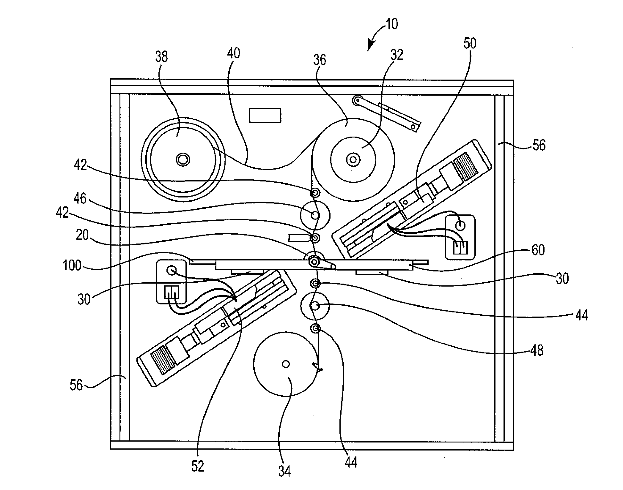
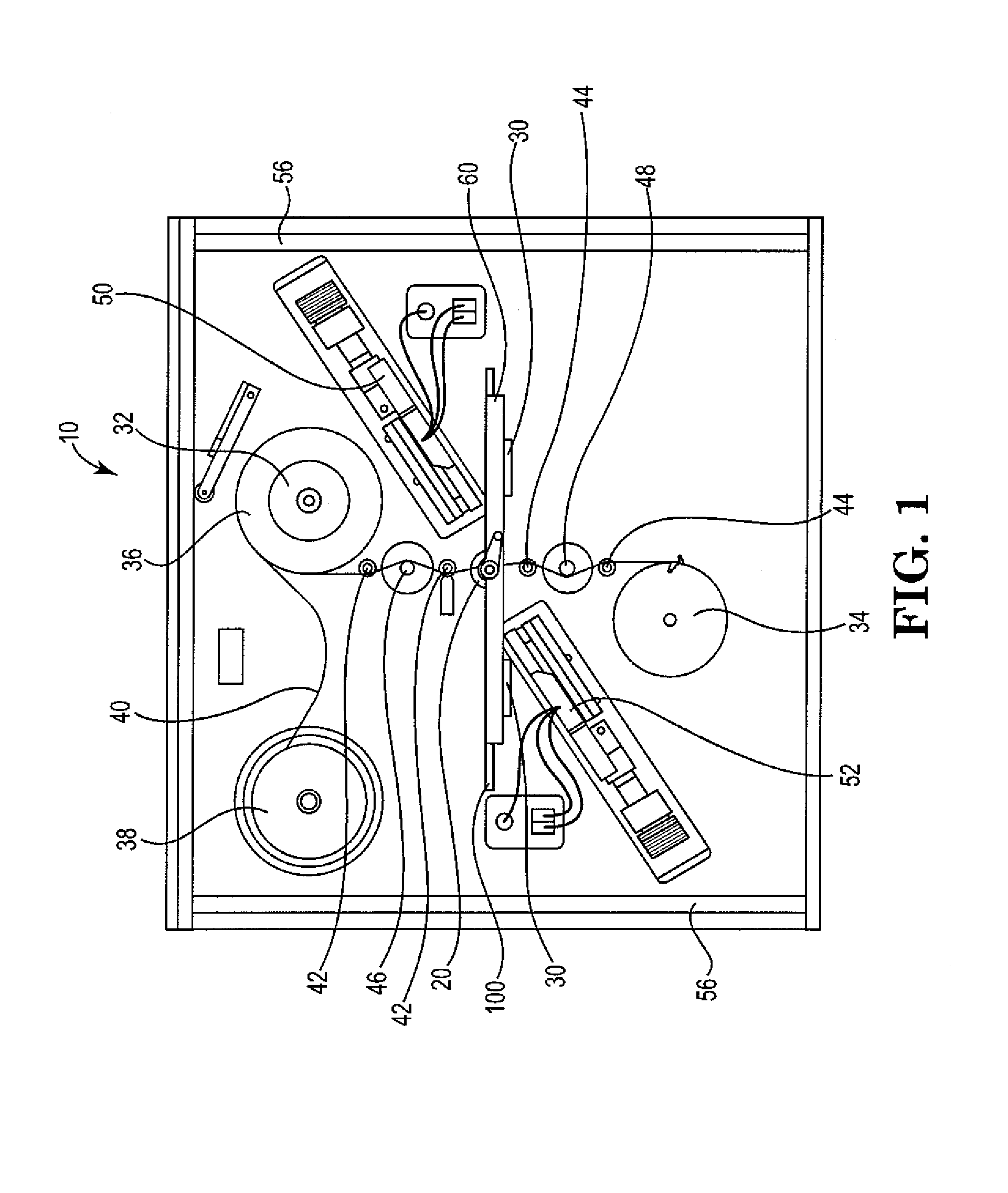
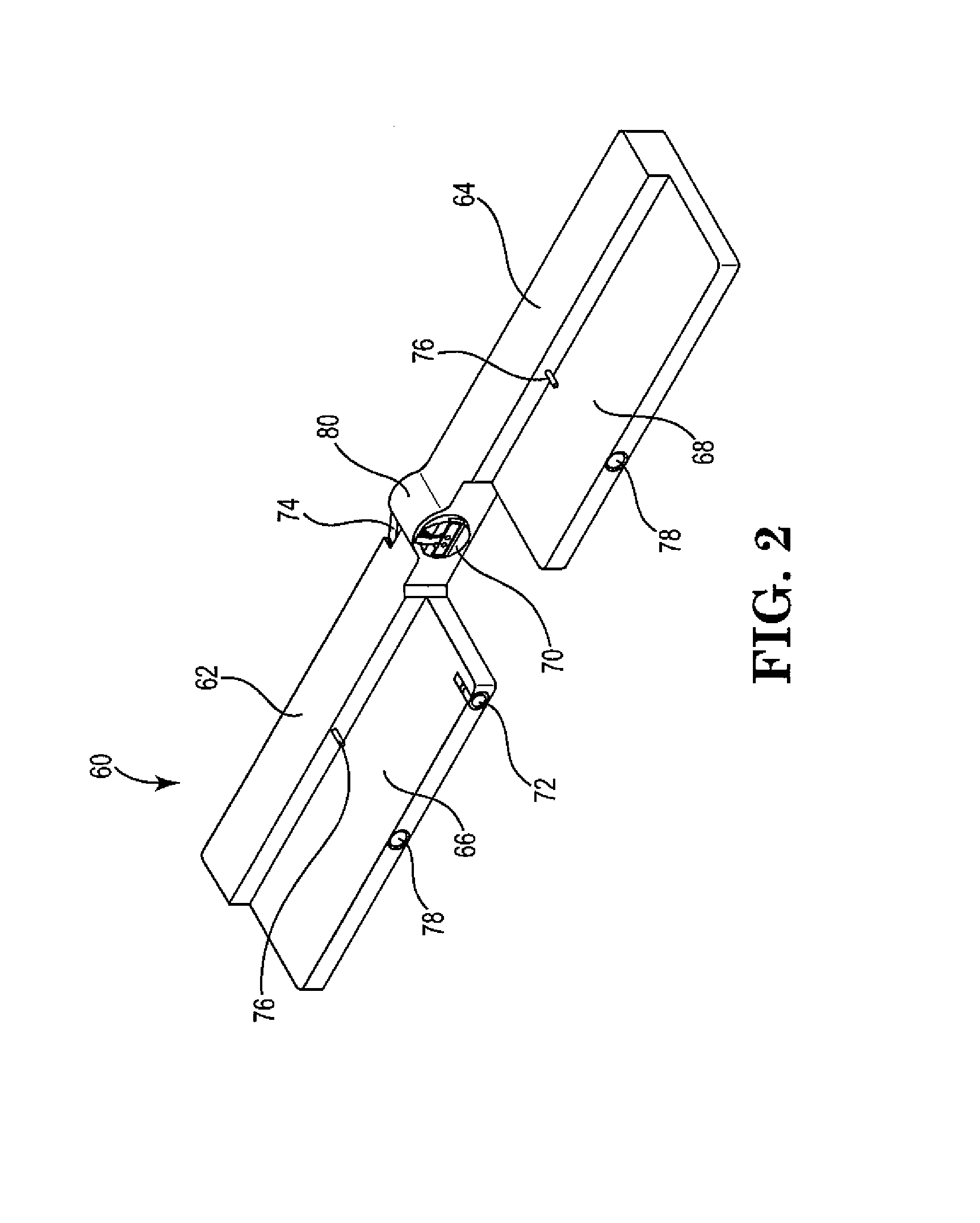
The present invention provides a device for automated coiling of a jelly roll electrode assembly. The device includes a winding apparatus, a platform for holding a battery mandrel, and a shuttle for inserting the mandrel into. The device can hold a battery mandrel and includes a base and a shuttle with a passage for a separator strip. The device can also include a feedback loop for tensioning the winding apparatus. The invention also provides a method for making an electrode assembly by coiling the electrodes around a battery mandrel and sealing the coil with a separator strip. The technical effects of the invention include controlled and consistent tensioning of the coiled electrodes during fabrication and improved efficiency in the production of battery assemblies.

Problems solved by technology

Batteries for medical devices have demanding requirements.
However, while the elimination of dead space should result in greater miniaturization, it also results in a greater difficulty of assembly due to the increasingly small size of the component parts.
However, removal of the mandrel from the core of the jelly roll inherently presents the potential of damaging the jelly roll due to the possibility of pulling the core of the jelly roll out with the mandrel.
Conversely, a loosely wrapped jelly roll wastes space and decreases battery capacity and power due to size constraints.
Oftentimes the coiling of the jelly roll can be complicated by telescoping of the coil, making the process inefficient.
In other instances, the jelly roll cannot be used due to deformation or tearing of the roll occurring during the coiling process.

Method used


Image

  • Coiling device for making an electrode assembly and methods of use
  • Coiling device for making an electrode assembly and methods of use
  • Coiling device for making an electrode assembly and methods of use

Examples


example 1

[0088

[0089]In operation, the coiler apparatus is used to make an electrode battery assembly by following these steps.

[0090]Ultra-Sonic Weld (USW) Electrodes to Mandrel[0091]1. Place mandrel in shuttle ligature. Locating (“P”) feature on mandrel, mate with reverse feature on clamp to ensure proper orientation.[0092]2. Insert ligature into shuttle.[0093]3. Orient shuttle on work table facing up.[0094]4. On positive side, open both large and small covers.[0095]5. Place positive electrode in channel and close large cover.[0096]6. With small cover open, adjust the “x” position (along the path of the track) of the electrode on the mandrel. Once placed properly, close small cover.[0097]7. Flip shuttle assembly over.[0098]8. Repeat steps 4-6 with negative electrode.[0099]9. Insert shuttle assembly into fixture at an ultra-sonic weld (USW) station. Locating pins on fixture line up with holes on shuttle for proper alignment.[0100]10. Perform weld of electrode to mandrel.[0101]11. Remove shutt...


PUM

PropertyMeasurementUnit
widthaaaaaaaaaa
widthaaaaaaaaaa
widthaaaaaaaaaa

Abstract

A system for the automated coiling of a jelly roll electrode assembly for controlled assembly and tensioning of jelly roll assembly is provided. The system includes: a shuttle, and a mandrel to which electrodes are welded; a base, mateable with the shuttle and on which the battery head assembly is mounted for welding to the mandrel; and a coiling device. The coiling device has an upper spool, a lower spool, holding a separator strip and a platform between the two holding the base. The separator strip is threaded through a passage in the mandrel separating positive and negative portions. Rotating the mandrel coils the positive electrode, the separator strip and the negative electrode to coil around the mandrel. The coiling device may include a feedback loop braking one or both spools and allowing the coiling tension to be programmed to a desired level.

Description

CROSS REFERENCE TO RELATED APPLICATIONS[0001]This application claims benefit under 35 U.S.C. §119(e) to U.S. Provisional Patent Application Ser. No. 61 / 390,431, filed Oct. 6, 2010, the contents of which is incorporated herein by reference in its entirety.FIELD OF THE INVENTION[0002]The invention relates to an automated battery assembly system utilizing a mandrel that allows for increased compactness and reproducibility.BACKGROUND OF THE INVENTION[0003]Batteries for medical devices have demanding requirements. They should be small, have a long life, high power output, low self-discharge rate, compact size and high reliability. The need for miniaturization while maintaining or increasing output means that as much of the battery footprint as possible should be used for power storage resulting in the concomitant elimination of dead space. However, while the elimination of dead space should result in greater miniaturization, it also results in a greater difficulty of assembly due to the ...

Claims


Application Information

Patent Timeline
Patent Type & Authority Patents(United States)
IPC IPC(8): B23P13/00H01M10/04H01M10/0525H01M50/531H01M50/543
CPCH01M2/26H01M10/0409H01M10/0525H01M2/305Y02E60/12Y10T29/49204Y10T29/49117Y10T29/10Y02E60/10H01M50/531H01M50/543Y02P70/50
Inventor VIAVATTINE, JOSEPH J.AAMODT, PAUL B.SAURKAR, SANDEEPSUARDINI, DONA M.TORGERSON, BRENT J.
Owner MEDTRONIC INC
Learn More