Back illuminated input device with selectively visible luminous patterns

a backlight input and luminous pattern technology, applied in the field of input devices, can solve the problems of further increase of fabricating costs, complicated printing process for coating light shading materials, and restrictions on the application of both conventional backlight input devices. , to achieve the effect of high backlight utilization efficiency

Inactive Publication Date: 2014-09-09
PRIMAX ELECTRONICS LTD
View PDF13 Cites 0 Cited by
  • Summary
  • Abstract
  • Description
  • Claims
  • Application Information

AI Technical Summary

Benefits of technology

[0006]The present invention is directed to an input device with luminous patterns, which has higher backlight utilization efficiency.
[0007]The present invention is also directed to an input device with luminous patterns, which is fabricated by a simpler process and thinner and lighter.
[0008]The present invention is further directed to an input device with luminous patterns, wherein the light shading materials thereof is not likely to fall off due to a long term use or wear and tear during transportation.

Problems solved by technology

However, both of the two conventional backlight input devices have restrictions in applications.
However, the screen printing process for coating the light shading materials is complicated, and thus the fabricating cost is further increased as well.

Method used


Image

  • Back illuminated input device with selectively visible luminous patterns
  • Back illuminated input device with selectively visible luminous patterns
  • Back illuminated input device with selectively visible luminous patterns

Examples


Embodiment Construction

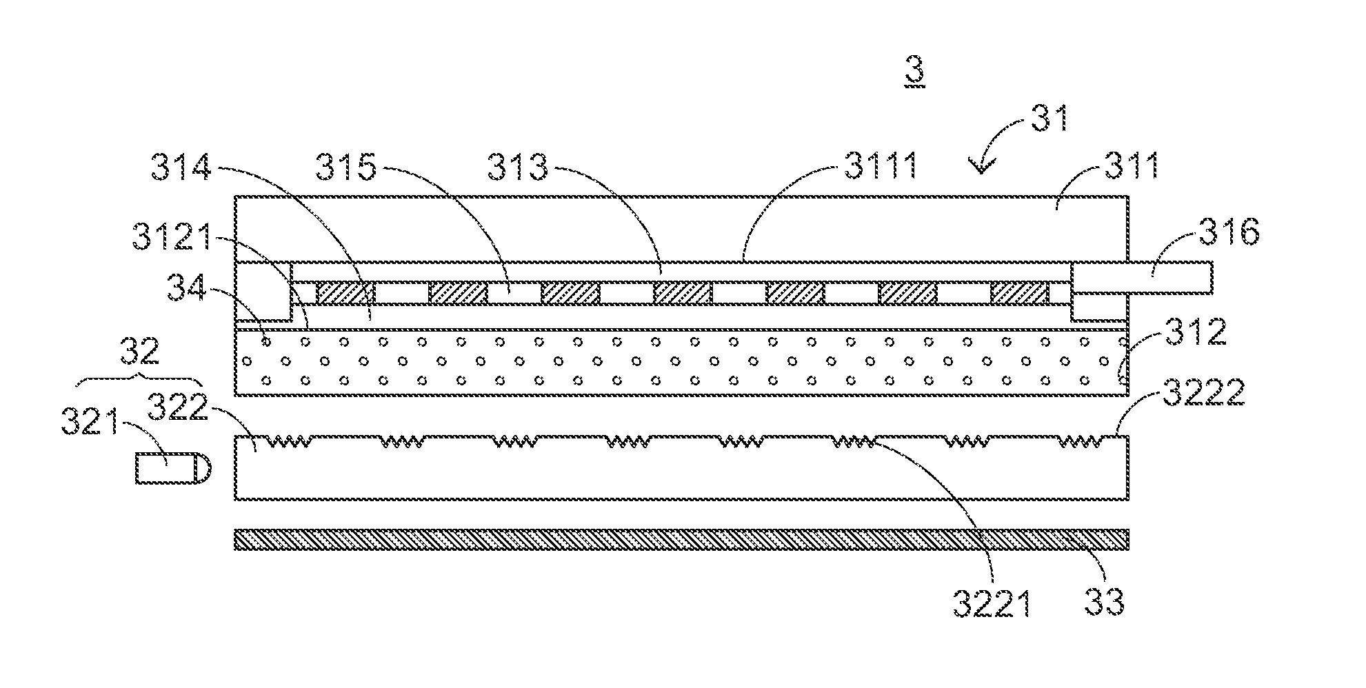
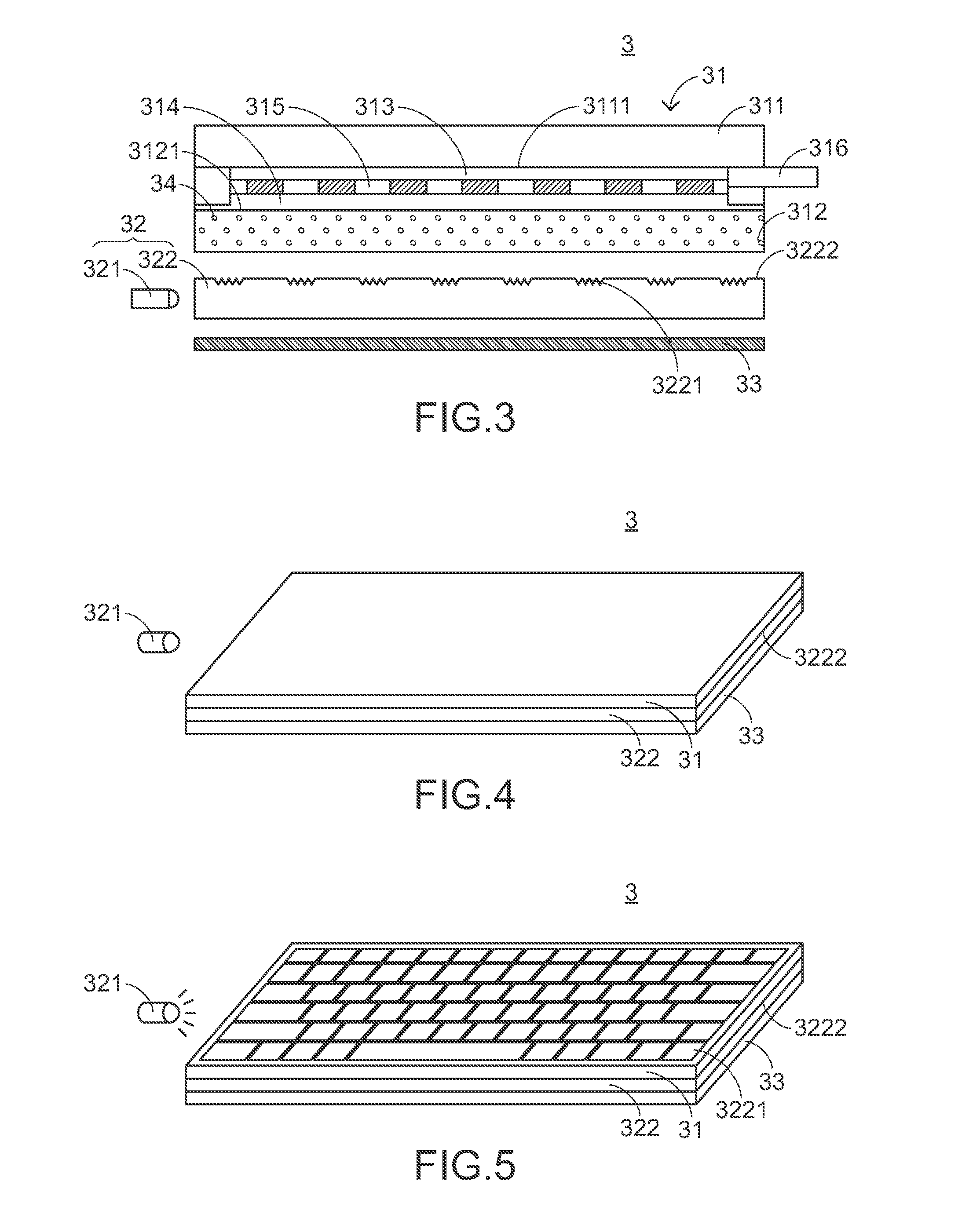
[0040]In view of the defects of the conventional arts, the present invention provides an input device with luminous patterns. FIG. 3 illustrates a structural side view of an input device with luminous patterns according to a first preferred embodiment of the present invention. Referring to FIG. 3, the input device 3 with luminous patterns comprises an input interface 31, a backlight module 32 and a black base plate 33, wherein a sequence from top to bottom thereof is the input interface 31, the backlight module 32 and the black base plate 33. The input interface 31 comprises a first substrate 311, a second substrate 312, a first transparent conducting film 313, a second transparent conducting film 314, a micro spot space layer 315 and a connector 316. The first substrate 311 is located over the second substrate 312, the first transparent conducting film 313 is disposed on a lower surface 3111 of the first substrate 311, and the second transparent conducting film 314 is disposed on a...


PUM


Abstract

The input device with luminous patterns includes an input interface and a backlight module. The backlight module includes a light source and a light guide plate. The input interface has a predetermined light shading rate and at least one pattern formed on the light guide plate. When the light source is turned off, the light passing through the light guide plate is too weak to show the pattern. When the light source is turned on, the luminous pattern is shown. One base plate of the input interface is made from a mixture of transparent plastic particles and light shading particles, and the at least one pattern is formed of the micro light guide structures.

Description

FIELD OF THE INVENTION[0001]The present invention generally relates to an input device, and more particularly to an input device with luminous patterns.BACKGROUND OF THE INVENTION[0002]Applications of the touch input device is quite extensive. Currently, some of the touch input device which is commercially available has two kinds of different input modes simultaneously. Herein, the touch input device has a backlight module, and a first input mode is provided when the backlight module is turned on and thus the touch input device shows a predetermined pattern, while a second input mode is provided when the backlight module is turned off and thus the predetermined pattern is not shown. In another word, users may recognize which input mode it is switched to currently by whether the pattern is shown or not, and then input signals according to the current input mode. For example, when the backlight is turned off, an appearance of the touch input device is presented as a whole black state ...

Claims


Application Information

Patent Timeline
Patent Type & Authority Patents(United States)
IPC IPC(8): G01D11/28
CPCG06F3/041G06F3/0418G02B6/0033G02B6/0036G06F3/0412G06F3/04182
Inventor CHEN, CHUNG-YUAN
Owner PRIMAX ELECTRONICS LTD
Why Eureka
Try Eureka