
Device for taking back empty containers, in particular plastic bottles and metal cans

a technology for empty containers and devices, applied in emergency equipment, instruments, aircraft ejection means, etc., can solve problems such as manual intervention

Active Publication Date: 2014-08-26
ENVIPCO HLDG
View PDF17 Cites 3 Cited by
  • Summary
  • Abstract
  • Description
  • Claims
  • Application Information

AI Technical Summary

Benefits of technology

[0004]Object of the present invention is to provide a generic device with which an almost unimpeded insertion of empty containers as bulk material into the intake chute is assured, wherein it is simultaneously prevented that excessively large objects can be inserted into the device.

Problems solved by technology

The disadvantage of this solution is that empty containers inserted as bulk material can accumulate on the grill, e.g., by getting stuck, and thereby prevent passage into the intake chute so that a large amount of manual intervention is required to ensure or restore admission into the intake chute.

Method used


Image

  • Device for taking back empty containers, in particular plastic bottles and metal cans
  • Device for taking back empty containers, in particular plastic bottles and metal cans
  • Device for taking back empty containers, in particular plastic bottles and metal cans

Examples


Embodiment Construction

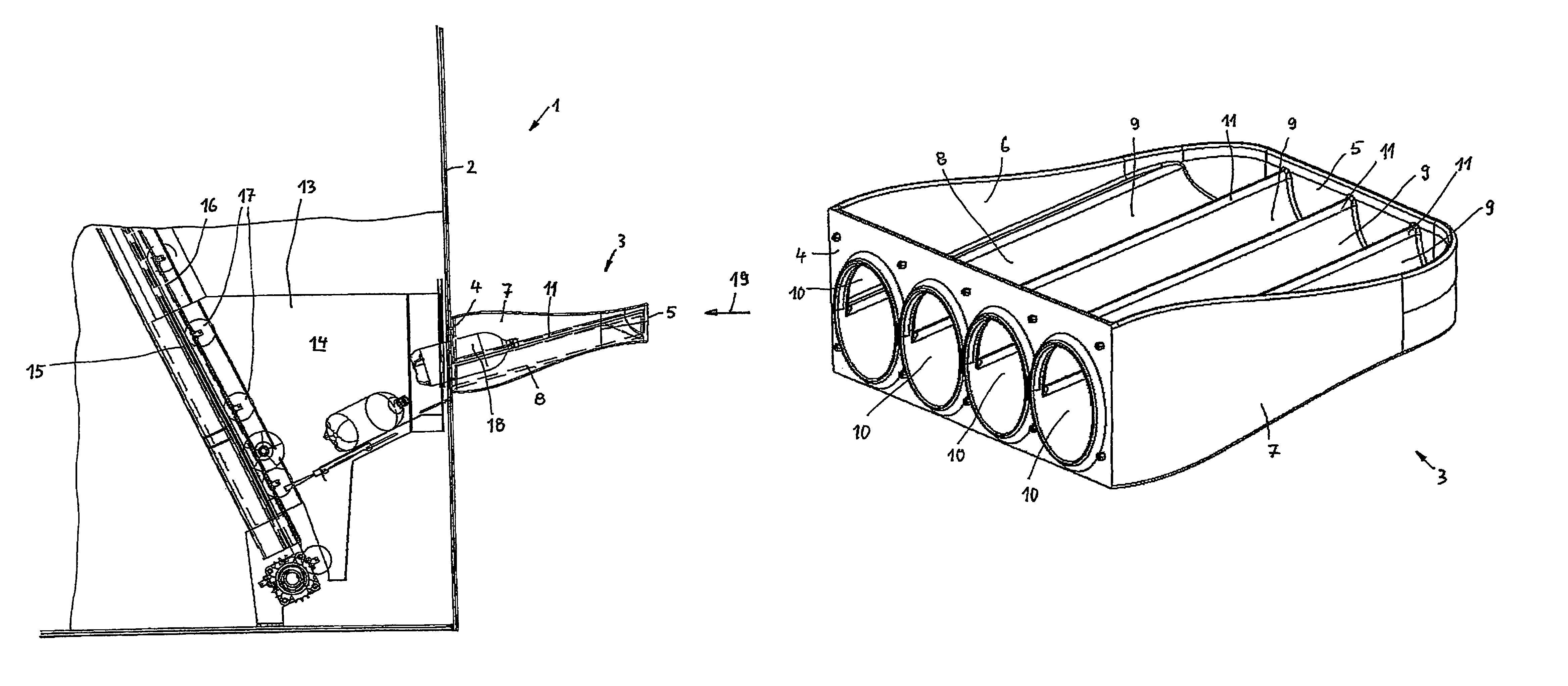
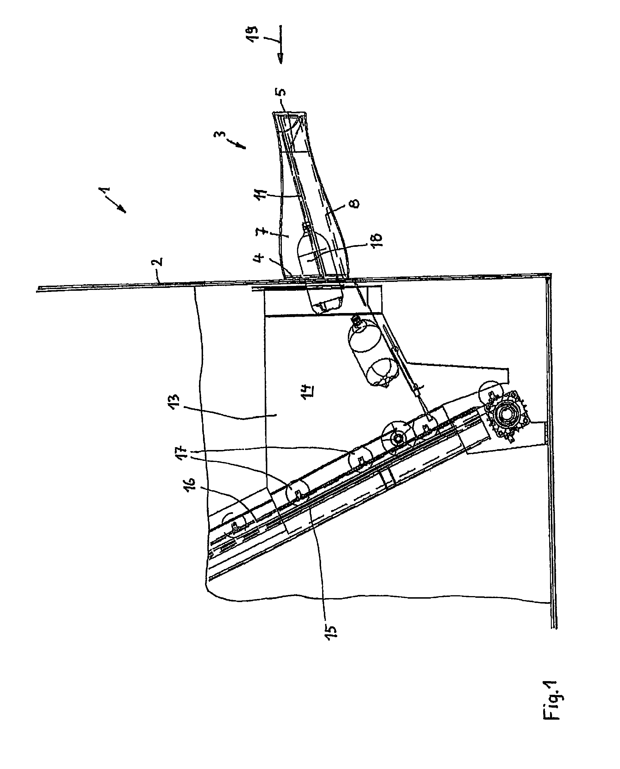
[0011]FIG. 1 depicts a section of a housing 1 of a device, otherwise not further pictured, for taking back empty containers 18. An intake chute 3 is attached externally to a perpendicular wall 2 of housing 1. In the region of the attachment location of this intake chute 3, housing 1 is cut away to render visible the internals arranged in housing 1 in this region.

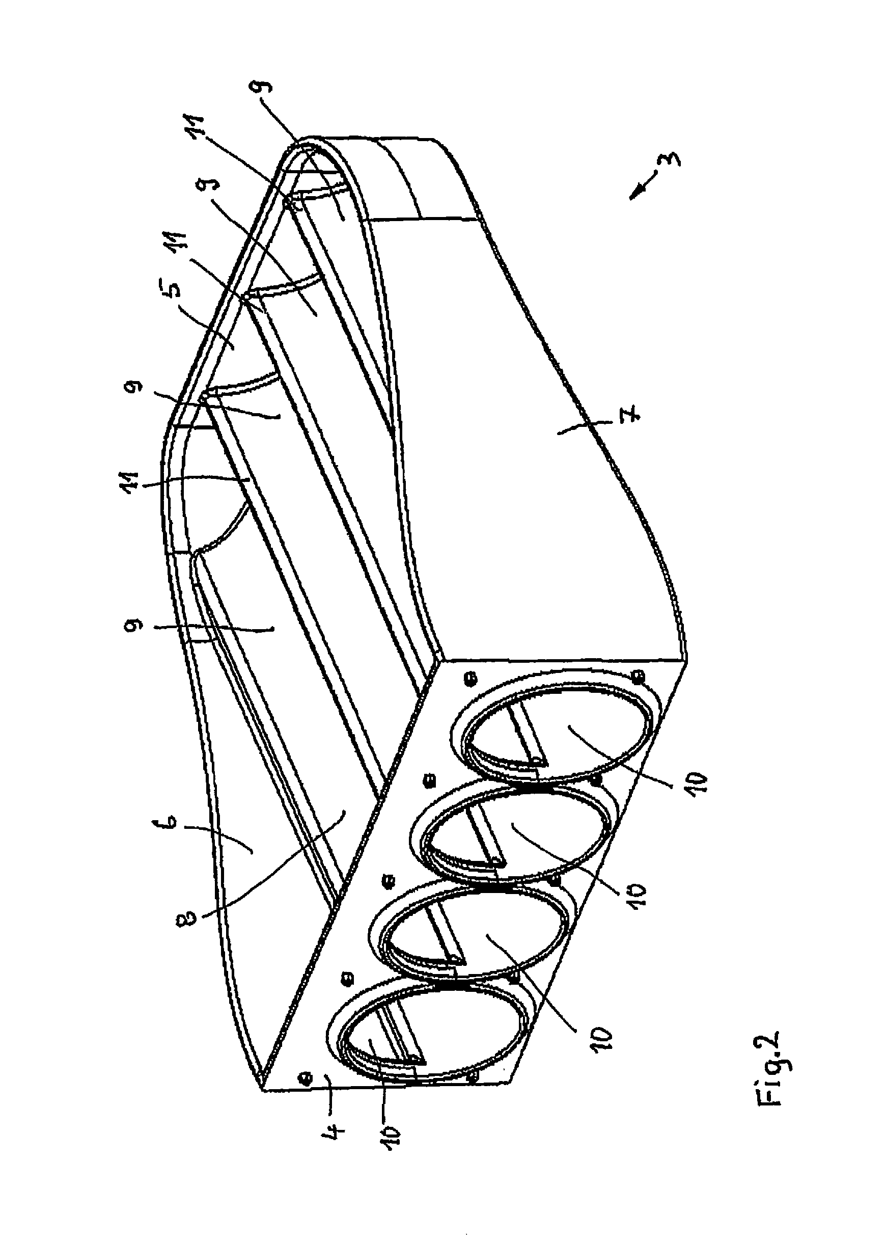
[0012]Intake chute 3 consists, in relation to the mounting position, of a back wall 4, a front wall 5, and two side walls 6 and 7, as well as a bottom 8 that is inclined downward by approximately 15° in the intake direction 19 (FIG. 1), in other words towards housing 1.

[0013]Bottom 8 is formed of four grooves 9 arranged side by side, which run between front wall 5 and back wall 4 and each have over their entire length a same cross-section, namely of a semi-circle. In back wall 4, grooves 9 each flow into a circular passage opening 10, whose radius corresponds to that of grooves 9. Adjoining grooves 9 directly merge into each...


PUM


Abstract

Device for taking back empty containers, in particular plastic bottles and metal cans, with a housing which has apparatuses for processing inserted empty containers, an intake chute accessible from the outside that receives empty containers as bulk material and a bottom sloping downward in direction of intake chute. Device is provided that prevents or impedes insertion of excessively large objects into device. Device provides almost unimpeded insertion of empty containers as bulk material into intake chute, and simultaneously prevents that excessively large objects can enter into the device. The bottom of intake chute has a plurality of grooves arranged side by side and running in the intake direction, the grooves flowing into a passage opening leading to the device and whose cross-section is dimensioned in such a manner that empty containers aligned longitudinally in the intake direction can pass unimpeded through the grooves.

Description

CROSS REFERENCE TO RELATED APPLICATIONS[0001]This application is a continuation of application no. PCT / DE2011 / 001857, filed Oct. 18, 2011, which claims the priority of German Application No. 10 2010 048 840.2, filed Oct. 18, 2010, and each of which is incorporated herein by reference.FIELD OF THE INVENTION[0002]The present invention relates to a device for taking back empty containers, in particular plastic bottles and metal cans according to the preamble of claim 1.BACKGROUND OF THE INVENTION[0003]Such a device is known from U.S. Pat. No. 4,505,370. This device serves in particular for taking back metal cans. It has a housing that encloses apparatuses that are used in the subsequent handling and if necessary processing of inserted cans. The device also has an intake chute accessible from the outside that takes in empty containers as bulk material and has a bottom that slopes downward in the intake direction. In order to prevent and hinder the insertion of excessively large objects,...

Claims


Application Information

Patent Timeline
Patent Type & Authority Patents(United States)
IPC IPC(8): B65G11/00B65G11/02G07F7/06
CPCB65G11/023G07F7/0609Y02W30/628Y02W30/62
Inventor HANDSCHICK, BERT
Owner ENVIPCO HLDG
Learn More