Anesthetic vaporizer and temperature compensation unit

a technology of anesthetic vaporizer and temperature compensation unit, which is applied in the direction of machines/engines, combustion types, lighting and heating apparatus, etc., can solve the problems of reducing the evaporation speed of the anesthetic agent, the evaporation speed of the liquid decreases, and the length is relatively short, so as to improve the temperature compensation effect

Active Publication Date: 2014-08-26
SHENZHEN MINDRAY BIO MEDICAL ELECTRONICS CO LTD
View PDF20 Cites 2 Cited by
  • Summary
  • Abstract
  • Description
  • Claims
  • Application Information

AI Technical Summary

Benefits of technology

[0009]The technical problem to be solved by some embodiments of the present invention is to provide an anesthetic vaporizer and a temperature compensation unit which can improve the temperature compensation effect.

Problems solved by technology

When the vaporizer is used continuously, the temperature of the vaporizer drops since the anesthetic agent has to absorb heat to vaporize, which in turn reduces the evaporation speed of the anesthetic agent since the evaporation speed of the liquid decreases as the temperature drops.
However, this type of compensation unit has disadvantages, such as the following: (1) the lower valve port assembly, which has a relatively short length, is only immersed into the upper space in the vaporizing chamber while remaining a certain distance away from the bottom of the vaporizing chamber.
During the anesthetic operation, when the liquid level of the anesthetic is below the bottom of the lower valve port assembly, the agent will no longer directly contact the metal valve seat of high temperature linear expansion coefficient, which is disadvantageous to heat exchange and reduces the compensation effect.
(2) Since the upper valve port assembly is installed with a plurality of metal rods which are required to be adjusted when the vaporizer is calibrated, the structure is complicated, and the requirements for installation and adjustment are accordingly relatively high, causing excessive difficulties and expense for installation and adjustment of the compensation unit.

Method used


Image

  • Anesthetic vaporizer and temperature compensation unit
  • Anesthetic vaporizer and temperature compensation unit
  • Anesthetic vaporizer and temperature compensation unit

Examples


Embodiment Construction

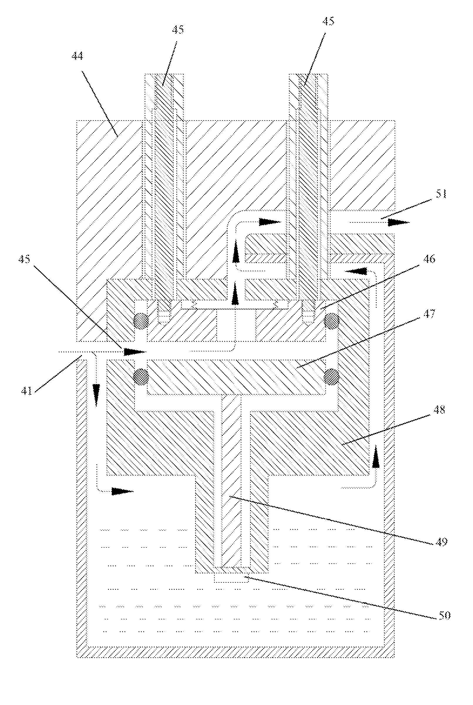
[0016]As shown in FIGS. 2-4, an anesthetic vaporizer according to an embodiment of the present disclosure may include a fresh gas inlet 1, a pressure compensation unit 2, a fresh gas cut-off valve 3, a wick unit 4, a bypass circuit 5, a temperature compensation unit 6, a concentration control unit 7, a mixed gas outlet 8, a filling unit 9, a vaporizing chamber 10 and a main gas path block 21. The pressure compensation unit 2 which serves to compensate for pressure can prevent gas from flowing reversely when the pressure at the mixed gas outlet 8 changes and stabilize the gas flow speed when the pressure at the fresh gas inlet 1 changes. The vaporizing chamber 10 may be implemented as a reservoir having a bottom wall 101 for storing liquid anesthetic agent. The wick unit 4, which may be positioned within the vaporizing chamber 10, may have a part thereof being immersed into the liquid anesthetic agent such that the liquid anesthetic agent can spread over the wick unit 4. The wick uni...


PUM


Abstract

An anesthetic vaporizer and a temperature compensation unit are disclosed. The temperature compensation unit, which cooperates with a vaporizing chamber having a bottom wall, includes a first device connected to the bottom wall of the vaporizing chamber for contacting with liquid anesthetic agent in the vaporizing chamber and changing in length according to temperature change of the liquid anesthetic agent, and a second device connected to the vaporizing chamber. A gas flow gap through which a gas flow passes is formed between the first and second devices. The gas flow gap becomes larger as temperature of the liquid anesthetic agent rises and smaller as the temperature of the liquid anesthetic agent drops. Since the first device is connected with the bottom wall of the vaporizing chamber, the first device will directly contact with the liquid anesthetic agent regardless of the liquid level of the anesthetic agent, as long as there is liquid agent in the vaporizing chamber; therefore the efficiency of heat exchange is high and the effect of temperature compensation is good.

Description

CROSS-REFERENCE TO RELATED APPLICATIONS[0001]The present application claims priority to Chinese Patent Application No. 200910105094.8, filed on Jan. 16, 2009, which is hereby incorporated by reference in its entirety.FIELD OF THE INVENTION[0002]The present disclosure relates to an anesthetic vaporizer and a temperature compensation unit.BACKGROUND OF THE INVENTION[0003]An anesthetic vaporizer is an apparatus that can be used to effectively vaporize a liquid anesthetic agent, and can precisely input the liquid anesthetic agent at a certain concentration into an anesthesia breathing circuit. The anesthetic vaporizer typically comprises a fresh gas inlet, a pressure compensation unit, a fresh gas cut-off valve, a wick unit, a bypass circuit, a temperature compensation unit, a concentration control unit, a mixed gas outlet, a filling unit, and a vaporizing chamber. The vaporizing chamber is a reservoir for storing liquid anesthetic agent. The wick unit is provided within the vaporizing ...

Claims


Application Information

Patent Timeline
Patent Type & Authority Patents(United States)
IPC IPC(8): F23D11/00A61M16/18
CPCA61M16/18A61M2205/3372
Inventor CHEN, DONGHUAGONG, DAOMINGQIAO, ZHIWEI
Owner SHENZHEN MINDRAY BIO MEDICAL ELECTRONICS CO LTD
Why Eureka
Try Eureka