Connecting device for electrical junction boxes

a technology of connecting device and electrical junction box, which is applied in the direction of coupling device connection, electrical apparatus, coupling/disengagement of coupling parts, etc., can solve the problems of operator discomfort, time-consuming, operator insufficient tightening of the ring, etc., and achieve the effect of easy production

Inactive Publication Date: 2014-08-19
PALAZZOLI
View PDF8 Cites 2 Cited by
  • Summary
  • Abstract
  • Description
  • Claims
  • Application Information

AI Technical Summary

Benefits of technology

The invention aims to provide a connecting device that is faster and easier to use than conventional systems. It is also designed to be easily produced using commonly available elements and materials. The technical effects of the invention include improved efficiency, ease of use, and cost-effectiveness.

Problems solved by technology

The connection system described above has the drawback of forcing the operator to perform an uncomfortable operation when tightening the ring at the end of the sleeve.
The operation is uncomfortable because it has to be carried out in a tight space, and is also rather time consuming.
Another drawback of the conventional system is that the operator might not tighten the ring sufficiently or might tighten it too much, in both cases causing an incorrect locking of the connection, with possible problems of tightness and reliability over time.

Method used


Image

  • Connecting device for electrical junction boxes
  • Connecting device for electrical junction boxes
  • Connecting device for electrical junction boxes

Examples


Embodiment Construction

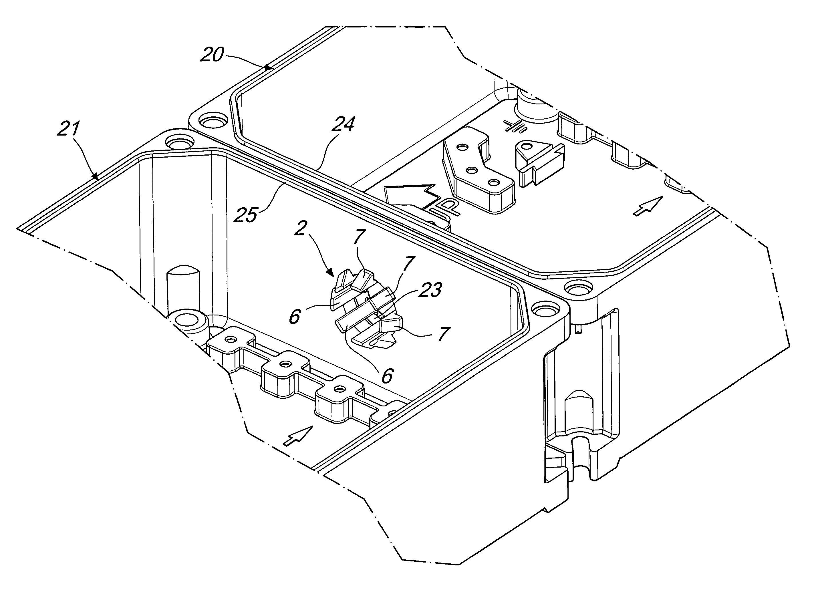
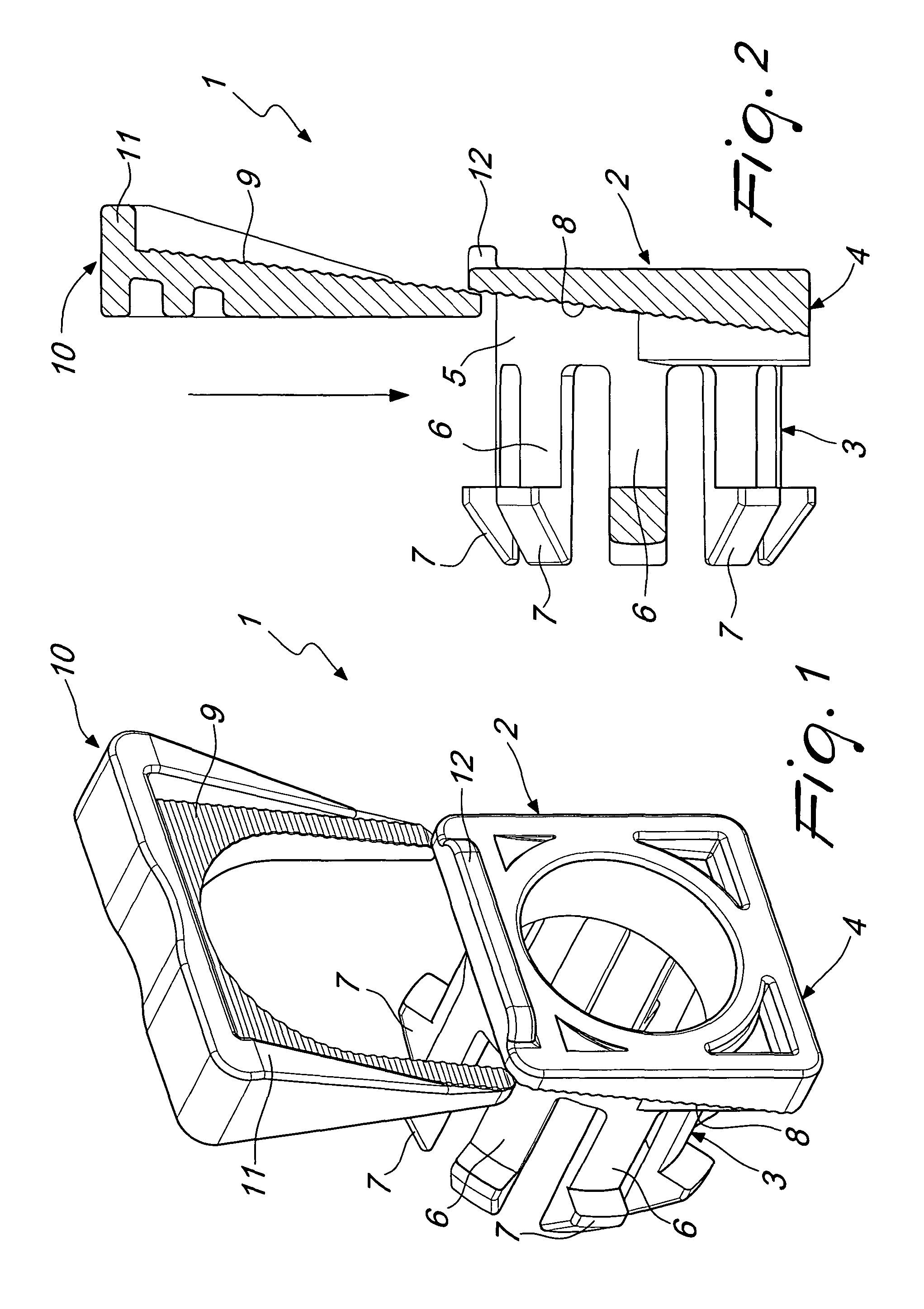
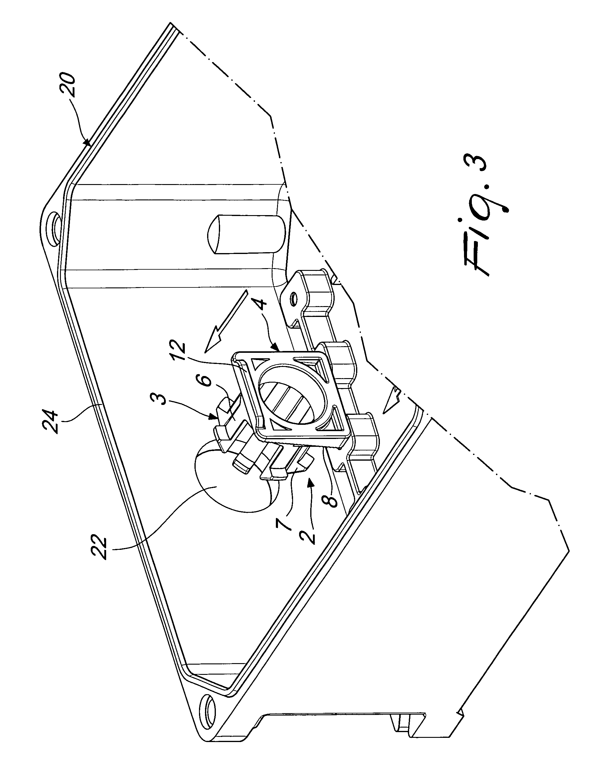
[0023]With reference to the cited figures, the device according to the invention, generally designated by the reference numeral 1, comprises a sleeve member 2 which is constituted by a substantially cylindrical body 3 and a plate 4. The sleeve member 2 is made of one piece.

[0024]The cylindrical body 3 has a base portion 5, which is joined to the plate 4, and a plurality of protrusions 6. Each protrusion 6 ends with a tooth 7.

[0025]Each tooth 7 has a front inclined guiding plane and a rear plane that lies at right angles to the directrix of the cylindrical body 3.

[0026]The plate 4 has a front inclined plane 8 extending around the base 5 of the cylindrical body 3, on the two sides of the plate and above the cylindrical body.

[0027]The inclined front plane 8 has a set of teeth constituted by teeth that lie horizontally.

[0028]The device 1 also comprises a wedge member 10, which is constituted by a fork body that has at least one rear inclined plane 9 adapted to cooperate with the incline...


PUM


Abstract

A connecting device for electrical junction boxes, including a sleeve member that can be inserted in a first hole of a first wall of a first box and in a second hole provided in a second wall of a second box to be joined to the first box. An annular gasket is fitted around the sleeve and is located between the two walls. The sleeve has a first end provided with a plate that is internal to the first box and a second end provided with an abutment means that engages the inner side of the second wall. The insertion of a wedge member, which is applied between the plate and the first wall, gradually moves the plate away from the inner side, pushing the walls against each other and compressing the gasket between them.

Description

BACKGROUND OF THE INVENTION[0001]The present invention relates to a connecting device for electrical junction boxes.[0002]Two adjacent electrical junction boxes are normally joined to each other by means of a threaded sleeve that is inserted in holes provided in the adjacent walls of the boxes to be joined.[0003]The sleeve is surrounded by a gasket, which is placed between the two adjacent walls.[0004]By tightening a ring on the sleeve, the two walls are moved mutually closer and compress the gasket, which thus provides the seal.[0005]The connection system described above has the drawback of forcing the operator to perform an uncomfortable operation when tightening the ring at the end of the sleeve.[0006]The operation is uncomfortable because it has to be carried out in a tight space, and is also rather time consuming.[0007]Another drawback of the conventional system is that the operator might not tighten the ring sufficiently or might tighten it too much, in both cases causing an i...

Claims


Application Information

Patent Timeline
Patent Type & Authority Patents(United States)
IPC IPC(8): H02G3/08
CPCH02G3/083H02G3/086
Inventor LEVI, BRUNO
Owner PALAZZOLI
Why Eureka
Try Eureka