
Parallelization of PLC programs for operation in multi-processor environments

a multi-processor environment and parallelization technology, applied in the direction of electrical programme control, program control, instruments, etc., can solve the problems of unbalanced parallelism across multiple processors, unoptimized arrangement, and limited understanding of how to compile iec 61131-3 languages for execution in multi-core processors, so as to minimize processing time, maximize cpu utilization, and minimize power consumption

Active Publication Date: 2014-08-05
SIEMENS AG
View PDF18 Cites 3 Cited by
  • Summary
  • Abstract
  • Description
  • Claims
  • Application Information

AI Technical Summary

Benefits of technology

The present invention is a method to analyze and optimize the execution of tasks in programming languages used for control of multi-core processors. It uses high-level language information to identify segments of tasks that can be distributed among multiple resources for efficient execution. This approach helps to minimize processing time, power consumption, and avoidCPU "starvation," while maximizing throughput and utilization of processor capabilities. The invention also utilizes the concept of time delay in PLC programs to create "slices" within specific function blocks and distribute them among available resources. Overall, the invention results in improved performance and better utilization of multi-core processors.

Problems solved by technology

Unfortunately, as of today, there is only a very limited understanding on how to compile IEC 61131-3 languages for execution in multi-core processors.
While this arrangement does utilize multiple processors in parallel, the efficiency of the arrangement is not optimum and there may be considerable periods of time where one or another of the processors is idle while another is over-demanded.
Again, while this automatic parallelization of a data flow program is useful in identifying portions that can be assigned to different processors, this partitioning occurs at a relatively high level (i.e., providing a “coarse grain” division), which results in a relatively unbalanced parallelism across the multiple processors.
If a program is written in a slightly obscure or different way, the compiler may fail to recognize one or more locations where partitioning may be applied.

Method used


Image

  • Parallelization of PLC programs for operation in multi-processor environments
  • Parallelization of PLC programs for operation in multi-processor environments
  • Parallelization of PLC programs for operation in multi-processor environments

Examples


Embodiment Construction

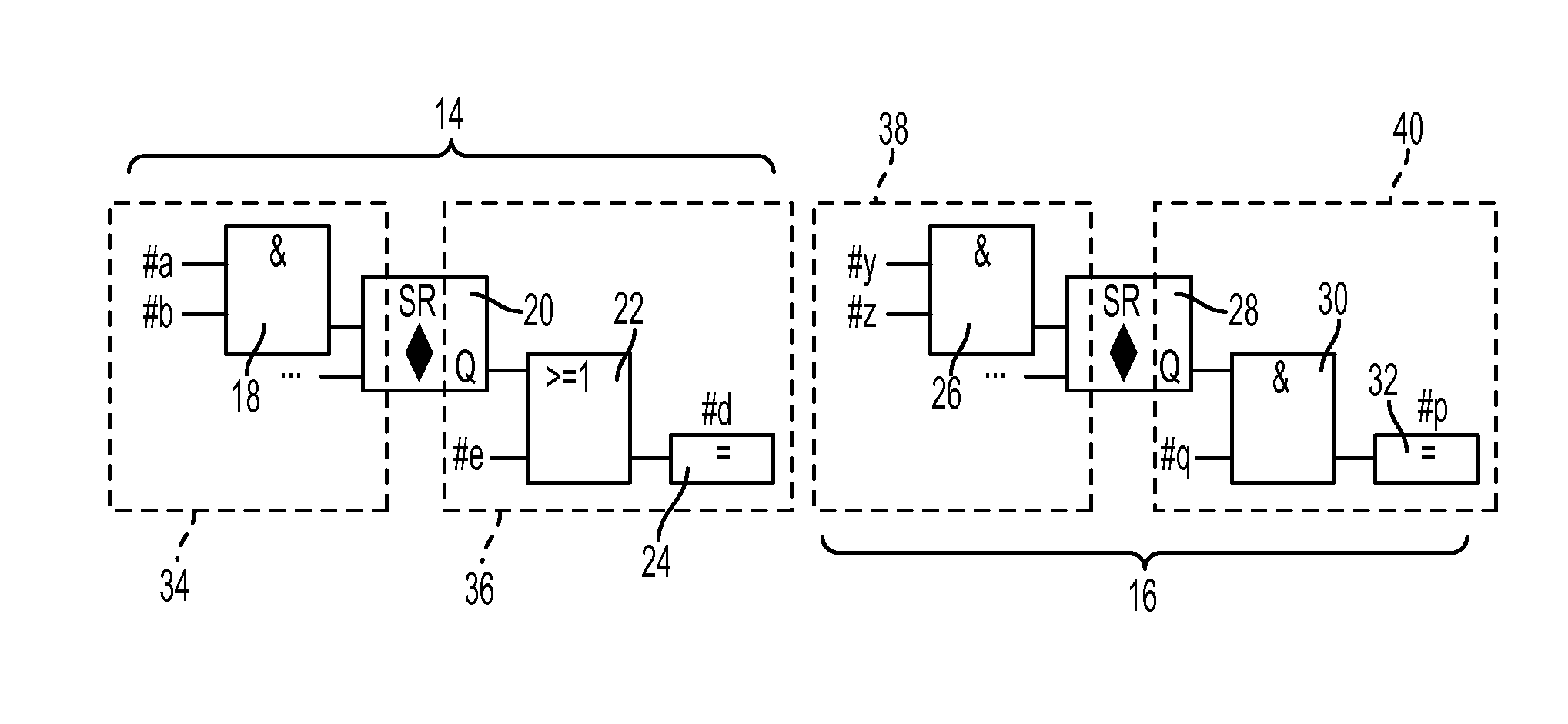
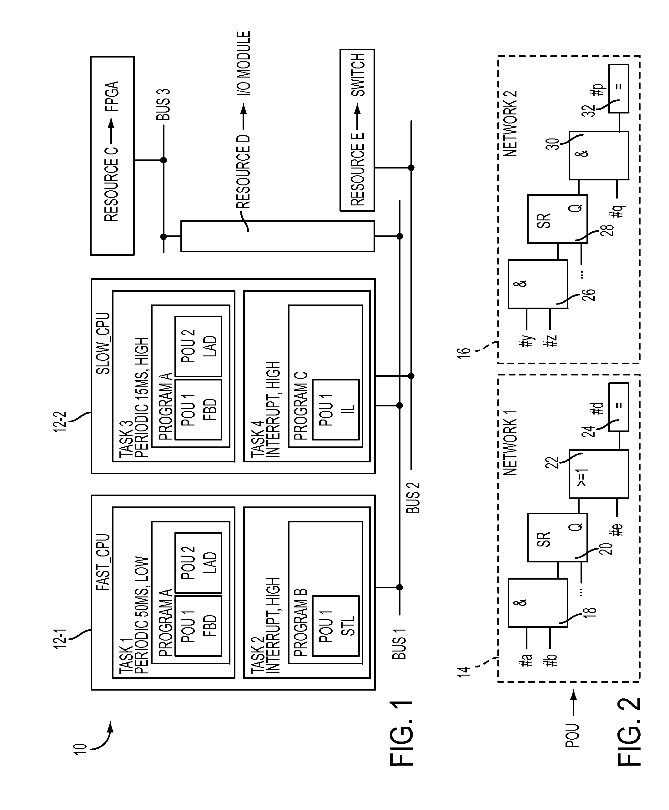
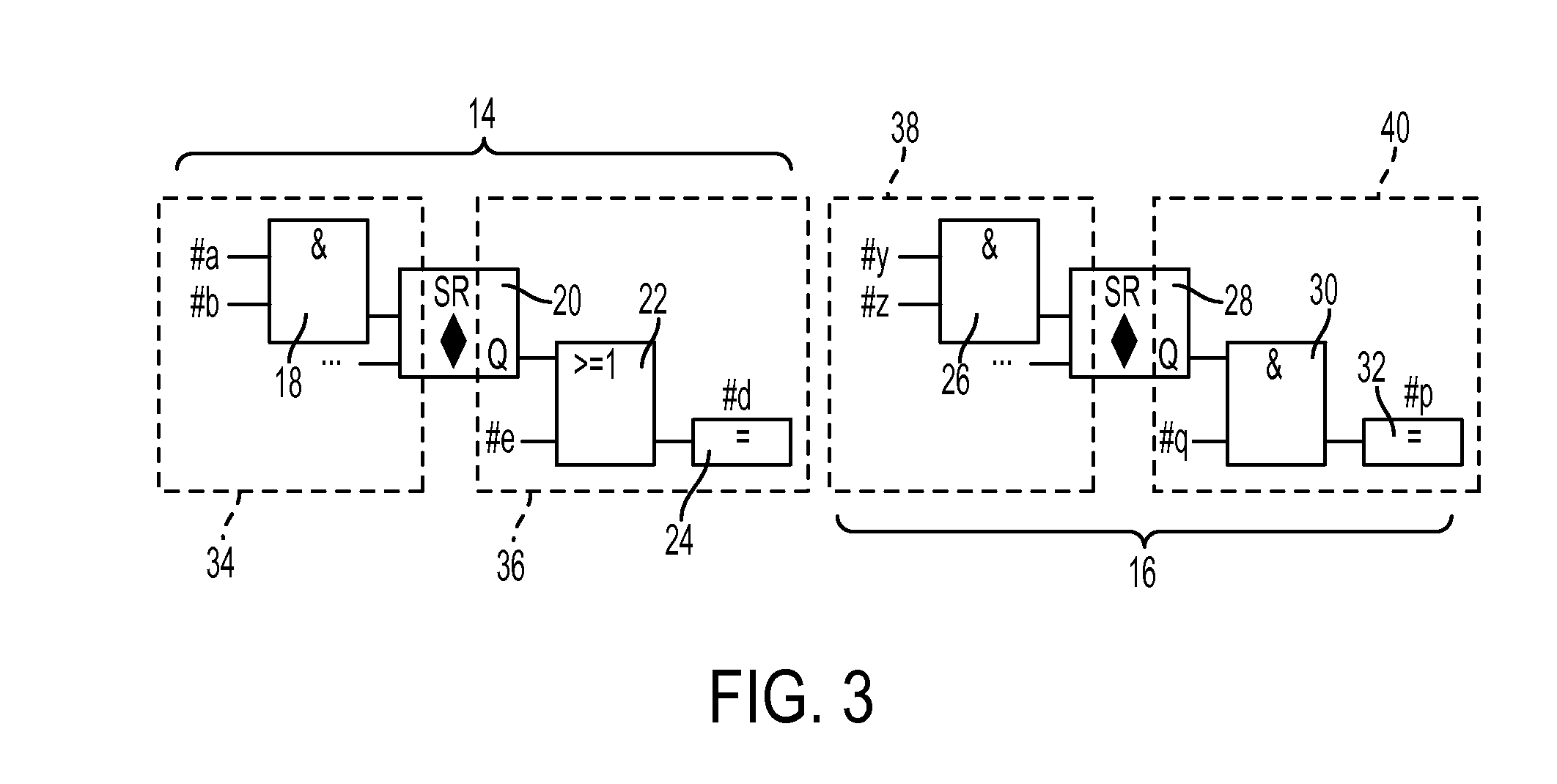
[0031]As will be described in detail hereinbelow, the present invention is directed to a method for automatically identifying and extracting parallelism from PLC programs written in high-level languages, the extracted parallelism preferably from both dataflow analysis and functional analysis, although the functional analysis of the present invention can indeed be performed independent of a dataflow analysis. These separate program fragments (tasks or sub-tasks) can then be assigned to different resources (such as different cores in a multi-core processor) and provide a well-balanced, efficient utilization of today's parallel processing environment.

[0032]Indeed, a significant aspect of the present invention is the realization that the functional information expressed in the high-level languages associated with IEC 61131-3 (hereinafter simply referred to as “PLC programs” for the sake of clarity and simplicity) can serve as a foundation for uncovering a significant amount of paralleli...


PUM


Abstract

A method of identifying and extracting functional parallelism from a PLC program has been developed that results in the ability of the extracted program fragments to be executed in parallel across a plurality of separate resources, and a compiler configured to perform the functional parallelism (i.e., identification and extraction processes) and perform the scheduling of the separate fragments within a given set of resources. The inventive functional parallelism creates a larger number of separable elements than was possible with prior dataflow analysis methodologies.

Description

CROSS-REFERENCE TO RELATED APPLICATIONS[0001]The application claims the benefit of U.S. Provisional Application No. 61 / 473,344, filed Apr. 8, 2011 and herein incorporated by reference.TECHNICAL FIELD[0002]The present invention relates to automatic parallelization of standardized industrial automation languages for execution in multi-core processors and, more particularly, to an automatic parallelization technique that relies on both dataflow analysis and functional analysis to create balanced parallelization across multiple processing resources.BACKGROUND OF THE INVENTION[0003]An industrial control system often includes a programmable logic controller (PLC) for providing coordinated control of industrial control equipment, which includes various elements that are often either sensors for providing inputs to the PLC, or relays for receiving outputs from the PLC, each under the control of an element controller, and each connected to the PLC over a network via a network I / O device. A P...

Claims


Application Information

Patent Timeline
Patent Type & Authority Patents(United States)
IPC IPC(8): G06F9/45G05B19/05G05B19/18
CPCG06F8/456G05B19/05
Inventor MARTINEZ CANEDO, ARQUIMEDESAL FARUQUE, MOHAMMAD ABDULLAHPACKER, MITCHELLFREITAG, RICHARD
Owner SIEMENS AG
Learn More