Ventricular volume reduction

a technology of ventricular volume and ventricular valve, which is applied in the field of medical/surgical devices, can solve the problems of reducing the effectiveness of the heart, back-up of pressure in the vascular system behind the ventricle, and millions of hospital visits to the hospital, so as to reduce the risk of clot formation, and enhance the strength and/or durability of the stru

Active Publication Date: 2014-07-29
EDWARDS LIFESCIENCES CORP
View PDF269 Cites 10 Cited by
  • Summary
  • Abstract
  • Description
  • Claims
  • Application Information

AI Technical Summary

Benefits of technology

[0016]In some variations the partitioning member is a membrane, as mentioned. This partitioning member may be configured so that it expands from a collapsed configuration to an expanded (ventricle-spanning) configuration. The ventricle-spanning configuration may be further adapted so that the surface is substantially smooth or free of irregularities. Such smooth surfaces may be preferable, since they may offer a lower risk of clot formation, for example, or for fluid dynamics considerations (e.g., decreasing turbulent flow). In some variations the partitioning membrane is formed of a plurality of overlapping members (e.g., leaves, etc.) that form the partitioning surface facing the active portion of the heart. For example, the parachute and fame may be constructed by cutting metal members (e.g., Nitinol) or relatively stiff, hard plastic members that may fan open or closed to expand / contract. In some variations, the membrane is formed of a relatively hard / stiff material (e.g., metal, thermoplastic, etc.) that is configured with hinged joints so that it may be collapsed for delivery and expanded once positioned. For example, the membrane may be formed of a relatively stiff material that folds along pre-determined edges. In other variations the partitioning member is a membrane that is secured to a frame (e.g., struts forming a membrane—supporting frame) only at the peripheral edge region of the partitioning member (e.g., membrane). This may allow the membrane to be held taut across the surface, rather than having the membrane to be anchored or secured more apically / distally relative to the rest of the implant.
[0018]Also described herein are implants including frames having one or more bridge struts. The bridge struts may couple adjacent struts to enhance the strength and / or durability of the struts once the device is in the implanted configuration.
[0024]In some variations the ventricular partitioning device may be configured to include one or more visualizable (e.g., under fluoroscopy, ultrasound, etc.) element. For example, the device may include a single strut that is configured to be visualized (e.g., coated with or formed by a radioopaque material). Such variations may be particularly useful for asymmetric devices. In some variations more than one strut may be marked for visualization. In some variations, the device may be marked with an oriented marker (e.g., an asymmetric shape) allowing better resolution of the three-dimensional orientation of the device even in a 2D fluoroscopic image. In some variations the device may be marked with words, phrases, images, icons, or the like.
[0026]Any of the strut variations described herein may be formed of two or more layers of material (e.g., formed by cutting two abutting layers of thin Nitinol material, such as two concentrically arranged tubes). The thin material may be cut to form two (or more) layers of struts. These struts may have different thicknesses. Processing may be improved by providing multiple relatively thin layers of near-overlapping material to form the struts, rather than a single thick layer (having an equivalent thickness to the multiple thin layers).
[0030]In some variations the membrane may encapsulate or surround portions of the device. For example, the edge of the membrane may be laminated back on itself to enclose or partially enclose a support element, a collapse element or the like (e.g., a string or suture). In some variations the different radial sections of the membrane may be separated by spacers to aid deployment. For example, the edge or rim region may include a metal or elastic polymer that helps the membrane fully deploy during operation. This spacer may also help seal the membrane to the wall of the ventricle, and may prevent the membrane from sticking to itself when the device is expanded from the collapsed configuration.

Problems solved by technology

Annually, heart failure leads to millions of hospital visits internationally.
In certain pathological conditions, the ventricles of the heart become ineffective in pumping the blood, causing a back-up of pressure in the vascular system behind the ventricle.
The reduced effectiveness of the heart is usually due to an enlargement of the heart.
A myocardial ischemia may, for example, cause a portion of a myocardium of the heart to lose its ability to contract.
Once this tissue dies, it no longer functions as a muscle and cannot contribute to the pumping action of the heart.
As this situation worsens, the local area of compromised myocardium may in fact bulge out as the heart contracts, further decreasing the heart's ability to move blood forward.
As the heart begins to fail, distilling pressures increase, which stretches the ventricular chamber prior to contraction and greatly increases the pressure in the heart.
Drug therapy typically treats the symptoms of the disease and may slow the progression of the disease, but it cannot cure the disease.
One of the only permanent treatments for heart disease is heart transplantation, but heart transplant procedures are very risky, extremely invasive and expensive and are performed on a small percentage of patients.
Many patient's do not qualify for heart transplant for failure to meet any one of a number of qualifying criteria, and, furthermore, there are not enough hearts available for transplant to meet the needs of heart failure patients who do qualify.
This procedure is highly invasive, risky and expensive and is commonly only done in conjunction with other procedures (such as heart valve replacement or coronary artery by-pass graft).
Additionally, the surgical treatment is usually only offered to the most severe class of patients and, accordingly, is not an option for most patients facing ineffective drug treatment.
Delivery of a partitioning device may be made complicated by the anatomy of a patient and by aspects or characteristics of the delivery device or partitioning device itself.

Method used


Image

  • Ventricular volume reduction
  • Ventricular volume reduction
  • Ventricular volume reduction

Examples


Embodiment Construction

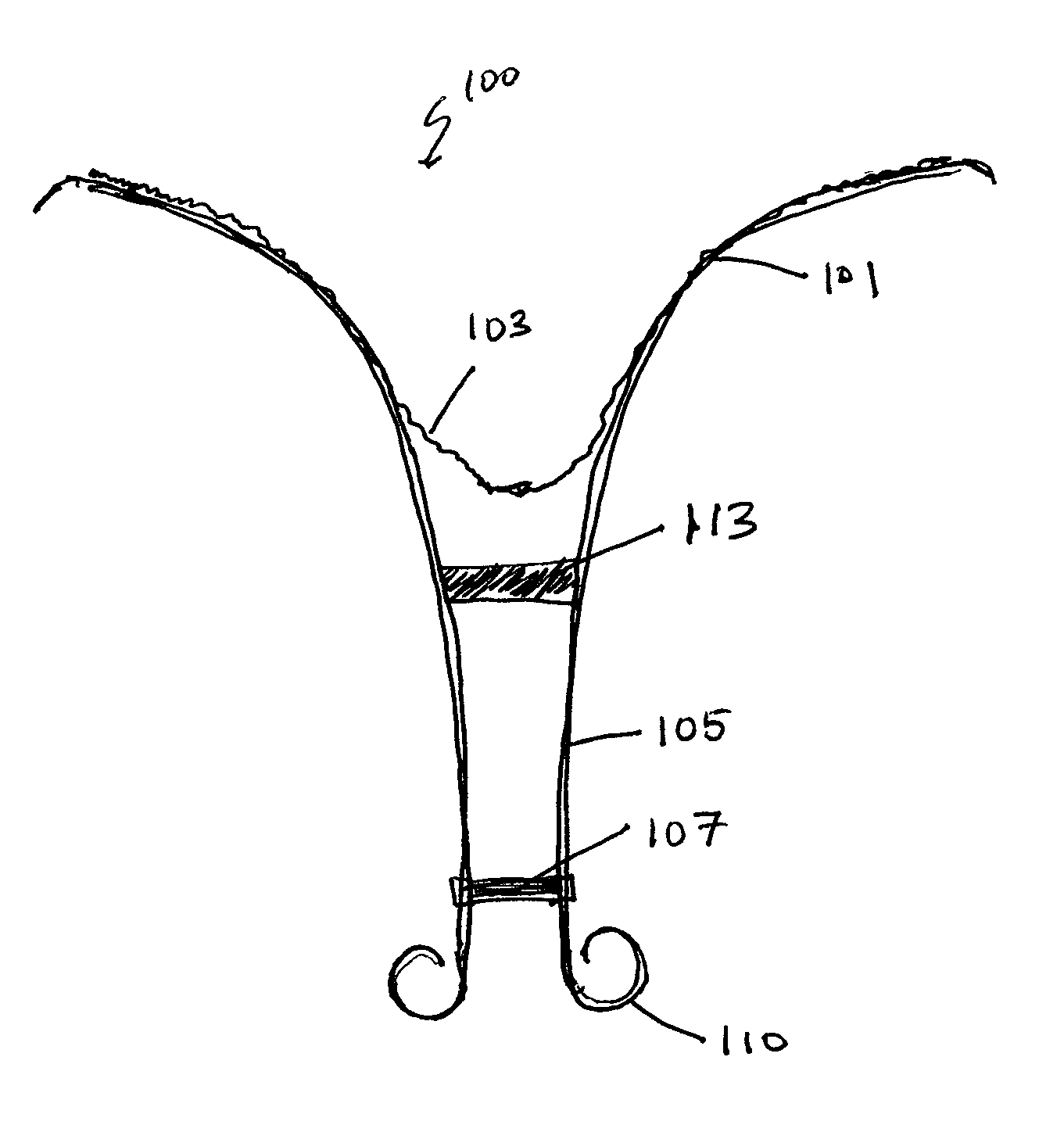
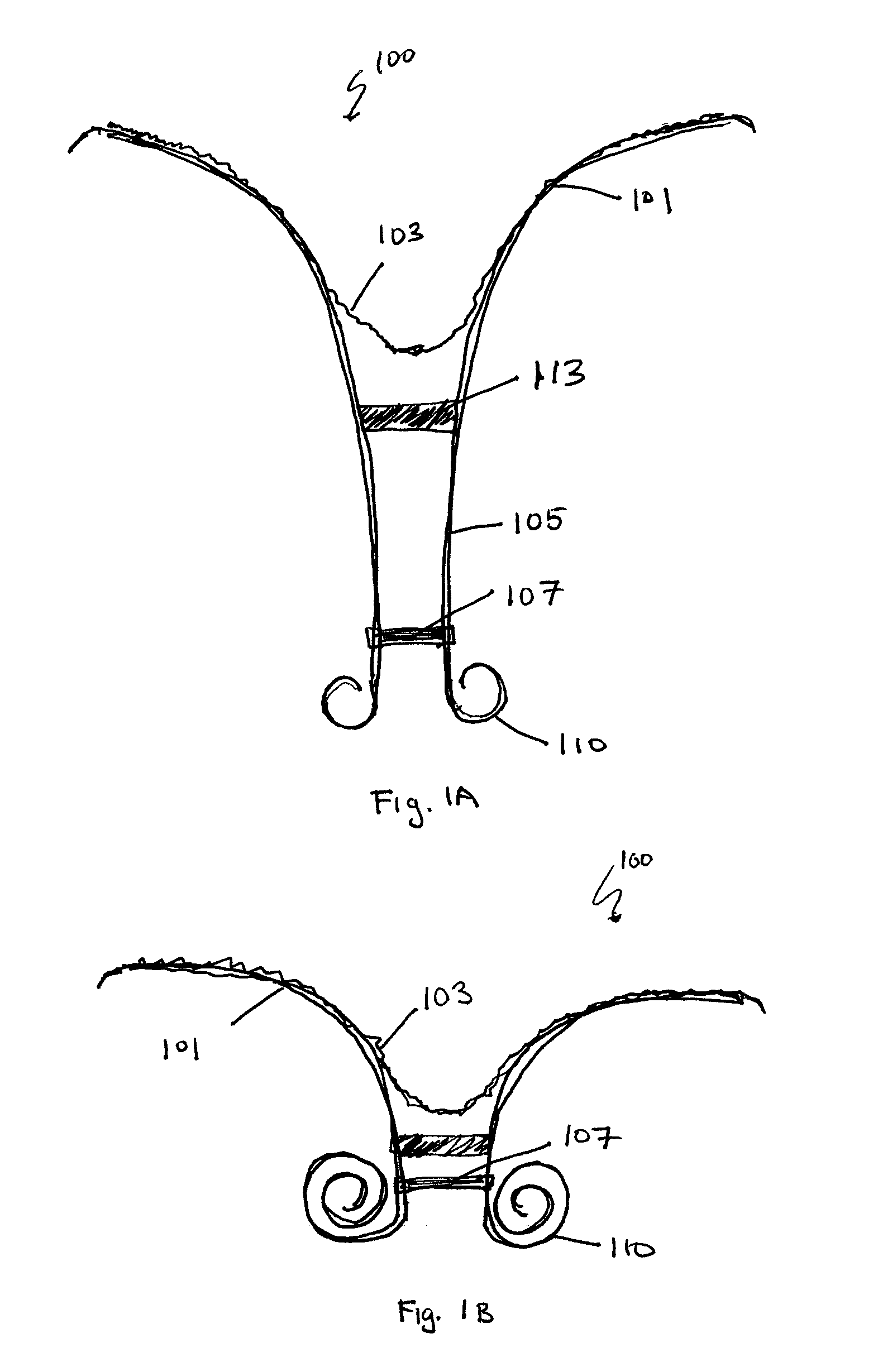
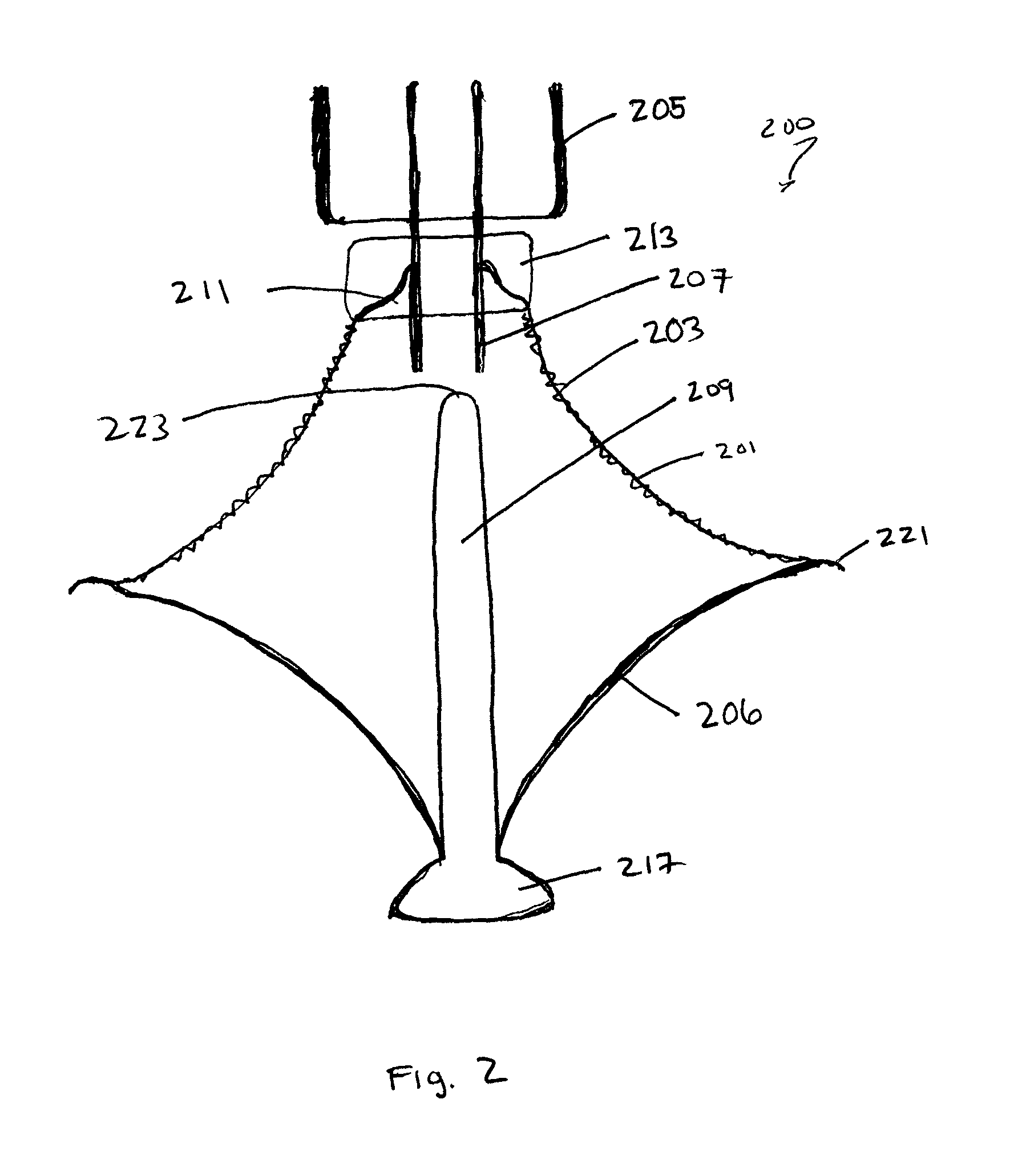
[0073]In general, described herein are implant for insertion into a patient's ventricle (e.g., left ventricle) to reduce ventricular volume by partitioning the ventricle into a productive and a non-productive portion. In some variations of these implants, a partitioning element, which may be a surface, extends at least partially across the diameter of the ventricle to partition the ventricle and thereby reduce the volume. In some variations the partitioning element is a membrane, which may be flexible. One or more supports may be used to support the membrane. An implant may also include one or more struts that can expand and collapse as necessary, and may span the diameter of the ventricle to position and / or anchor the partitioning element across the ventricle. In general, these implants may be delivered in a low-profile collapsed configuration and expanded in the ventricle to reduce the volume of the ventricle.

[0074]For example, in some variations the implants include a partitionin...


PUM


Abstract

Devices and systems including implants (which may be removable) and methods of using them for reducing ventricular volume. The implants described herein are cardiac implants that may be inserted into a patient's heart, particularly the left ventricle. The implant may support the heart wall, or may be secured to the heart wall. The implants are typically ventricular partitioning device for partitioning the ventricle into productive and non-productive regions in order to reduce the ventricular volume.

Description

CROSS REFERENCE TO RELATED APPLICATIONS[0001]This application claims priority to U.S. Provisional Patent Application Ser. No. 61 / 255,018, filed on Oct. 26, 2009, titled “VENTRICULAR VOLUME REDUCTION,” which is herein incorporated by reference in its entirety.[0002]The devices and methods described herein may be applied to many of the devices and systems described in any of the references listed below. In particular, these references generally describe devices, systems, and methods for improving cardiac function and to ventricular partitioning devices in particular. Thus, the following patents / patent applications are herein incorporated by reference in their entirety: U.S. patent application Ser. No. 09 / 635,511, titled “DEVICE AND METHOD FOR TREATMENT OF HOLLOW ORGANS,” filed on Aug. 9, 2000; U.S. patent application Ser. No. 10 / 212,032, titled “METHOD FOR IMPROVING CARDIAC FUNCTION,” filed on Aug. 1, 2002; U.S. patent application Ser. No. 10 / 212,033, titled “DEVICE FOR IMPROVING CARD...

Claims


Application Information

Patent Timeline
Patent Type & Authority Patents(United States)
IPC IPC(8): A61F2/00A61M60/17A61M60/295A61M60/497A61M60/865
CPCA61B17/12122A61B17/12172A61M1/106A61M1/1074A61F2/2487A61M1/125A61M2205/32A61M60/17A61M2207/00A61M60/865A61M60/867A61M60/295A61M60/289A61M60/497A61M60/861A61M60/468A61M60/47A61B2017/0053A61M25/0068A61M25/0067A61M60/274A61M60/833
Inventor KERMODE, JAMES R.ALEXANDER, MILES D.BOUTILLETTE, MICHAEL P.DAVILA, MATTHEW T.TAN, IRENE BING BIE
Owner EDWARDS LIFESCIENCES CORP
Why Eureka
Try Eureka