
Low-profile right-angle electrical connector assembly

a right-angle, low-profile technology, applied in the direction of electrical apparatus, coupling device connection, printed circuit, etc., can solve the problems of inability to use, reduce the speed and processing of data, and unsatisfactory latency, so as to reduce the diameter of the network, reduce the number of hops, and improve the effect of performan

Active Publication Date: 2014-07-22
AIRBORN
View PDF73 Cites 27 Cited by
  • Summary
  • Abstract
  • Description
  • Claims
  • Application Information

AI Technical Summary

Benefits of technology

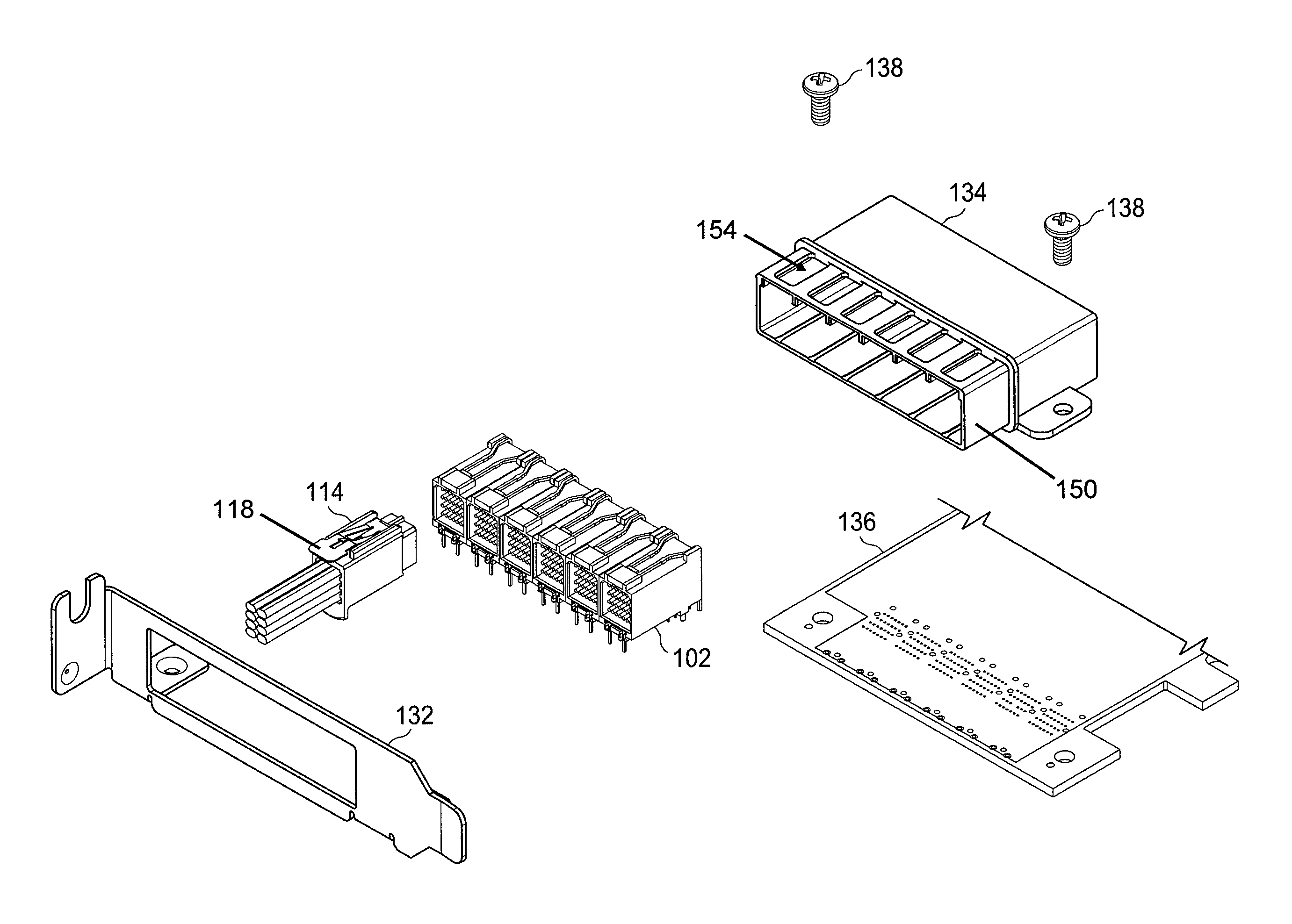
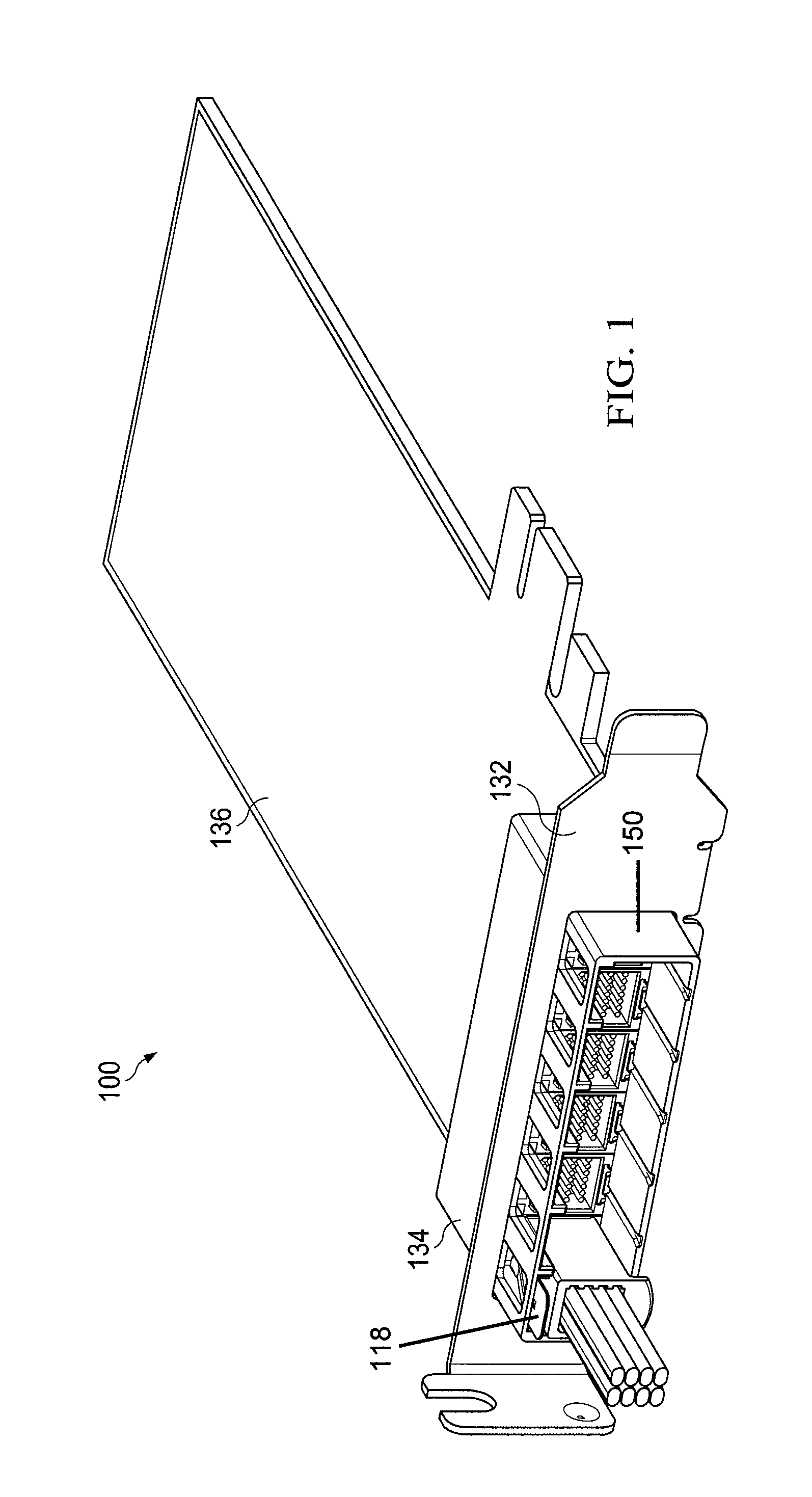
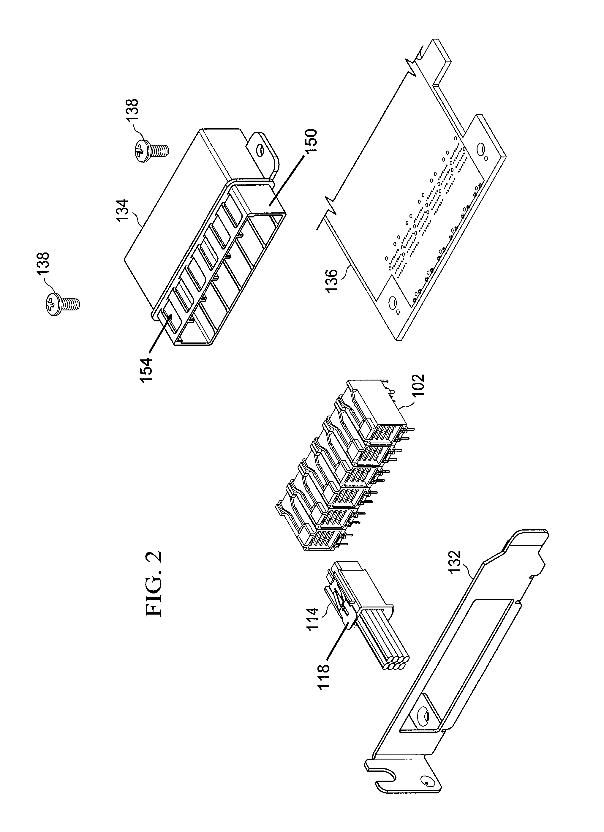
The invention provides a low-profile right-angle connector assembly with six board-mount connectors that allow cable connectors to connect to a low-profile PCIe card. The use of six connectors allows for more complex interconnection topologies, reduces latency, and cost benefits. The connector assembly includes an LED display for visual confirmation of link status. The various embodiments of the invention improve capabilities and efficiencies, particularly with standard high density servers, including simplified cabling, lower power consumption, lower operation costs, and improved fault tolerance and reliability. The connector cover includes a latch opening and a resilient latch for securely securing the cover to the connector. The latch can engage with hook supports, slots, or guide tabs on the connector to ensure a secure connection. The connector cover is made of a material that protects it from electromagnetic interference.

Problems solved by technology

Traditional low-profile PCIe card connector assemblies only contain four board-mount connectors because the connectors are too large to allow six connectors to fit in the space required by the PCIe specification.
These traditional connector assemblies result in undesirable latency (i.e., reduction in the speed and processing of data) and cannot be used to create complex topologies like 3D Torus or Flat Butterfly networks because these multidimensional network topologies need 24 lanes of signals, i.e. a total of 48 differential pairs of signal contacts.
Considering that most modern servers used in datacenters are designed to accommodate only low-profile PCIe cards, using standard connectors would not enable the realization of the type of power reduction and efficiency improvements afforded by low-profile PCIe with a total of 48 differential pairs of signal contacts.

Method used


Image

  • Low-profile right-angle electrical connector assembly
  • Low-profile right-angle electrical connector assembly
  • Low-profile right-angle electrical connector assembly

Examples


Embodiment Construction

[0034]The figures described above and the written description of specific structures and functions below are not presented to limit the scope of what Applicants have invented or the scope of the appended claims. Rather, the figures and written description are provided to teach any person skilled in the art to make and use the inventions for which patent protection is sought. Those skilled in the art will appreciate that not all features of a commercial embodiment of the inventions are described or shown for the sake of clarity and understanding. Persons of skill in this art will also appreciate that the development of an actual commercial embodiment incorporating aspects of the present inventions will require numerous implementation-specific decisions to achieve the developer's ultimate goal for the commercial embodiment. Such implementation-specific decisions may include, and likely are not limited to, compliance with system-related, business-related, government-related and other c...


PUM


Abstract

A low-profile, right angle connector assembly comprises six cable connectors and six board-mount connectors housed within a PCIe bracket and EMI shell. The PCIe bracket and EMI shell are braced to a low profile PCIe card. Each board-mount connector is designed to receive a cable connector and allows for the transmission and processing of high-speed data with lower latency. A removable latch mounted on the cable connectors helps ensure the cable connectors remain physically connected to the board-mount connectors. The removable latch may be replaced as needed for breakage and wear and tear.

Description

CROSS REFERENCE TO RELATED APPLICATIONS[0001]The present application is a continuation-in-part of co-pending U.S. patent application Ser. No. 13 / 296,166, entitled “Low-Profile Right-Angle Electrical Connector Assembly,” filed Nov. 14, 2011; and a continuation-in-part of co-pending U.S. patent application Ser. No. 13 / 296,174, entitled “Insulator with Air Dielectric Cavities for Electrical Connector,” filed Nov. 14, 2011; and a continuation-in-part of co-pending U.S. patent application Ser. No. 13 / 296,179, entitled “Electrical Connector with Wafer Having Inwardly Biasing Dovetail,” filed Nov. 14, 2011; all of which are incorporated herein by reference in their entireties.BACKGROUND OF THE INVENTION[0002]1. Field of Invention[0003]The present invention is directed to a low-profile right angle electrical connector assembly having six board-mount connectors that allow for the right angle connection of cable connectors to a low profile Peripheral Component Interconnect Express (“PCIe”) ca...

Claims


Application Information

Patent Timeline
Patent Type & Authority Patents(United States)
IPC IPC(8): H01R12/00
CPCH01R25/006H01R12/724H01R13/627H01R12/7082H01R12/716H01R13/6275
Inventor SOUBH, EMADSMITH, JASONBILLI, EMILIOGRANT, JOHN
Owner AIRBORN
Learn More