Inkjet textile printing method and inkjet textile printing apparatus
a textile printing and inkjet technology, applied in printing, typewriters, textiles and paper, etc., can solve the problems of inability to print with the proper tone of color, inability to print with the correct tone, etc., to achieve the effect of increasing the size and complexity of the apparatus, reducing the cost of printing, and increasing space and other factors
- Summary
- Abstract
- Description
- Claims
- Application Information
AI Technical Summary
Benefits of technology
Problems solved by technology
Method used
Image
Examples
first embodiment
A. First Embodiment
A-1. Apparatus Constituent Features
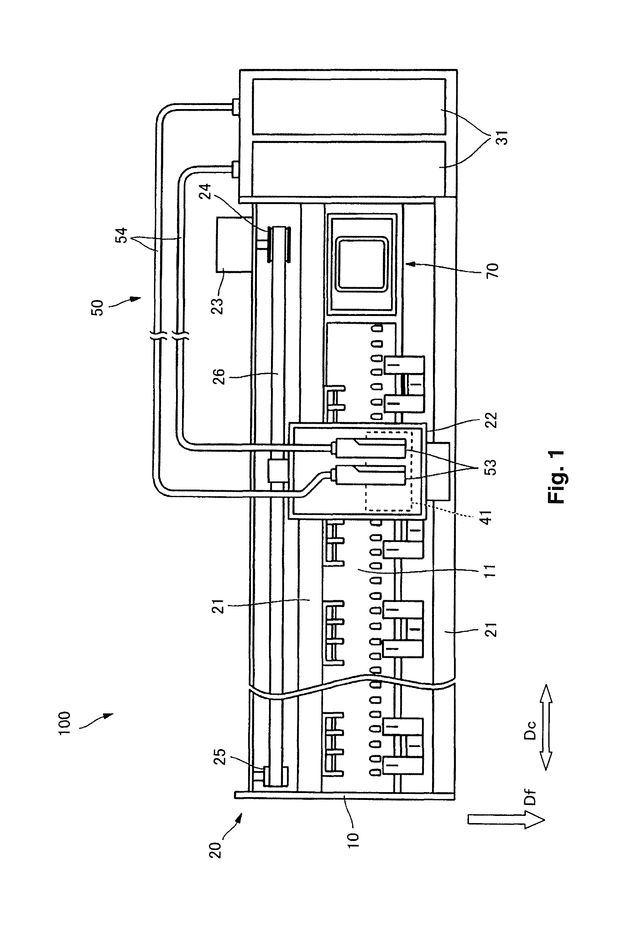
[0078]FIG. 1 schematically illustrates constituent features of an inkjet printer 100 according to a first embodiment of the present invention. In FIG. 1, a portion of the constituent parts are omitted and the dimensions of some parts are changed as appropriate in order make the constituent features of the inkjet printer 100 easier to understand.
[0079]The inkjet printer 100 of this embodiment is a printing apparatus that can execute inkjet textile printing so as to record an image by ejecting ink toward a surface (printing surface) of a fabric serving as a recording medium PM. As will be explained later, the inkjet printer 100 of this embodiment discharges a penetrant liquid toward the printing surface of the fabric in order to decrease a difference of image density between a printing surface and an opposite-side surface (non-printing surface) while suppressing ink bleeding. In this embodiment, the term “image” includes letters, s...
second embodiment
B. Second Embodiment
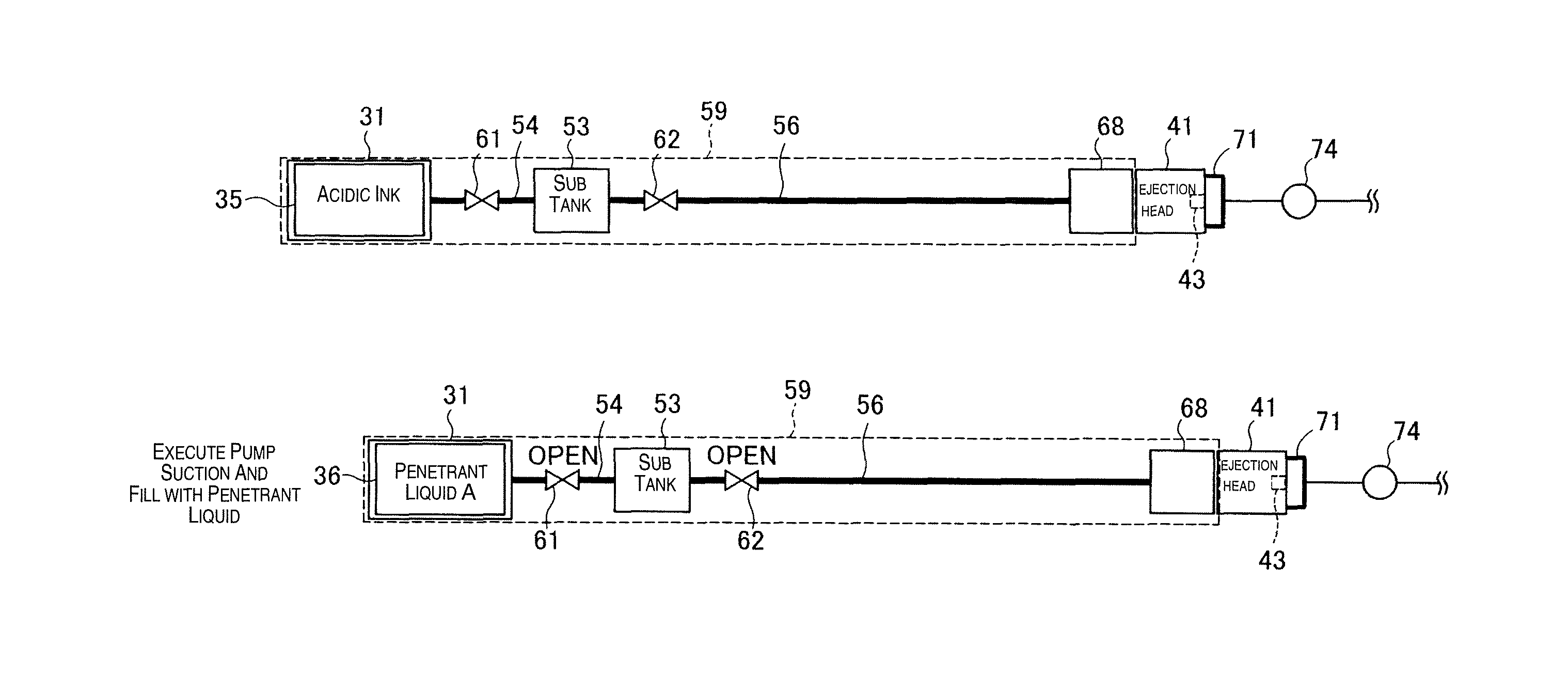
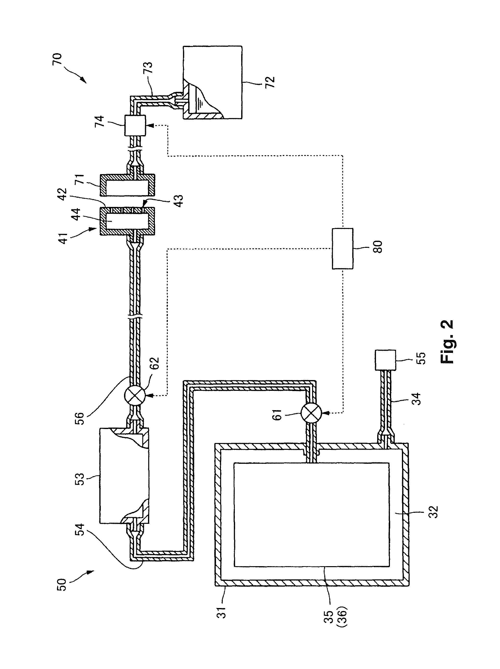
[0202]FIG. 18 schematically illustrates constituent features of a liquid supply system 50 according to a second embodiment. The liquid supply system 50 of the second embodiment has bypass pipes 67 connecting from positions between the first valve 61 and the sub tank 53 of the first supply pipes 54 of the subordinate liquid supply systems 59 for penetrant liquid to positions between the first valve 61 and the sub tank 53 of the first supply pipes 54 of the subordinate liquid supply systems 59 for the different colors of ink. In the example shown in FIG. 18, the first supply pipes 54 for the black (Bk), cyan (C), and magenta (M) inks are connected with bypass pipes 67 to one of the first supply pipes 54 for the penetrant liquid, and the first supply pipes 54 for the yellow (Y), the light cyan (LC), and the light magenta (LM) inks are connected with bypass pipes 67 to the other first supply pipe 54 for the penetrant liquid. Each of the bypass pipes 67 is equipped wi...
third embodiment
C. Third Embodiment
[0210]FIG. 21 illustrates constituent features of an ejection head 41 of an inkjet printer 100 according to a third embodiment. In the third embodiment, the ejection head 41 includes an ink head 41I and a penetrant liquid head 41P. Ink nozzle lines 45 are formed in the nozzle face 42 of the ink head 41I, and penetrant liquid nozzle lines 45 are formed in the penetrant liquid head 41P. The penetrant liquid head 41P is positioned upstream of the ink head 41I in the subordinate scanning direction Df.
[0211]The printing process is the same in the third embodiment as in the first embodiment (FIG. 5). However, in the third embodiment, the ejections of penetrant liquid and the ejections of ink onto each position of the recording medium PM are separated into preceding and subsequent main scans instead of executed during the same main scan. More specifically, the penetrant liquid is ejected onto each position of the recording medium PM during a main scan and the inks are ej...
PUM
| Property | Measurement | Unit |
|---|---|---|
| temperature | aaaaa | aaaaa |
| temperature | aaaaa | aaaaa |
| temperature | aaaaa | aaaaa |
Abstract
Description
Claims
Application Information
 - R&D
- Intellectual Property
- Life Sciences
- Materials
- Tech Scout
- Unparalleled Data Quality
- Higher Quality Content
- 60% Fewer Hallucinations
Browse by: Latest US Patents, China's latest patents, Technical Efficacy Thesaurus, Application Domain, Technology Topic, Popular Technical Reports.
© 2025 PatSnap. All rights reserved.Legal|Privacy policy|Modern Slavery Act Transparency Statement|Sitemap|About US| Contact US: help@patsnap.com


