Method and apparatus for wrapping a coil

Inactive Publication Date: 2004-03-16
APPLIED TECH GROUP
View PDF19 Cites 35 Cited by
  • Summary
  • Abstract
  • Description
  • Claims
  • Application Information

AI Technical Summary

Benefits of technology

So far as the present invention is concerned, the most pertinent of the prior art in this area are Clein and Clein et al., supra, helically wrap a rotating annulus by repeatedly passing a roll of wrapping material around successive radial portions of said annulus. These inventors have provided a wrapping apparatus comprising an endless oval track composed of two sections which are separated to allow insertion of a portion of the oval track through the hollow center core of the steel coil, after which the two sections are reunited. A self-propelled shuttle continuously travels around the resulting endless track. The shuttle carries a roll of wrapping material, which is applied to the slowly rotating coil as a long, continuous helical strip. A complex series of fixed and biased rollers are incorporated into the shuttle to maintain tension on the coil wrap, thereby increasing the size and complexity of the shuttle. While effective so far as prior inventions go, these patents have numerous and important disadvantages.
In accordance with at least one illustrative embodiment, a wide range of gauges, or thickness, of stretch wrap is accommodated by providing variable amounts of tension to the wrap via a simple, compact, continuously-adjustable tensioning device built into each handle holding the roll, which can be quickly and easily adjusted by the operator.

Problems solved by technology

A complex series of fixed and biased rollers are incorporated into the shuttle to maintain tension on the coil wrap, thereby increasing the size and complexity of the shuttle.
While effective so far as prior inventions go, these patents have numerous and important disadvantages.
One major disadvantage of their disclosed systems is the complexity of the equipment, i.e., the track and supporting structure needed is large and cumbersome.
Clein et al., supra, move the coil on conveyer carriages from which they are lifted by drive rollers, an exceedingly complicated arrangement.
Moreover, to house an endless track tall enough to handle the largest coils, both patents have resorted to cumbersome superstructures, several stories tall, that pose a potential physical hazard to overhead cranes.
A further disadvantage of both patents is the time required to wrap the coil.
Obviously, for smaller coils, the time wasted during each lap of the shuttle around the track accumulates into a good deal of time wasted for the wrapping the entire coil, and continues to accumulate when large batches of smaller coils are being wrapped.
Other disadvantages are inherent in their systems as well.
For example, the aforementioned complex tensioning rollers on the shuttle to stretch the wrap are cumbersome and costly.
They are also difficult to adjust and time consuming to reload when the wrap either runs out or is severed, e.g., due to adverse operating factors such as excessive tensioning of the wrap.

Method used


Image

  • Method and apparatus for wrapping a coil
  • Method and apparatus for wrapping a coil
  • Method and apparatus for wrapping a coil

Examples


Embodiment Construction

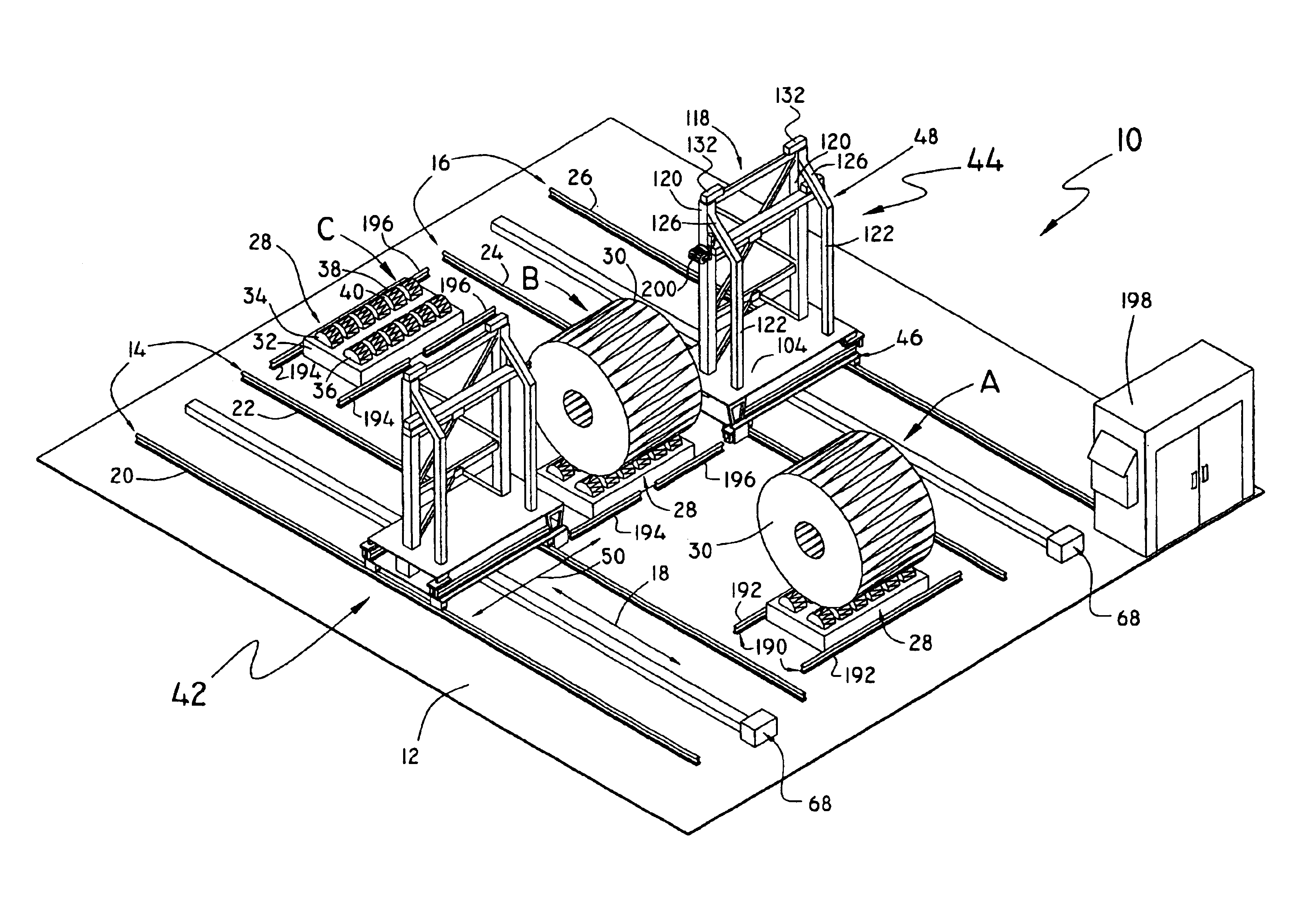
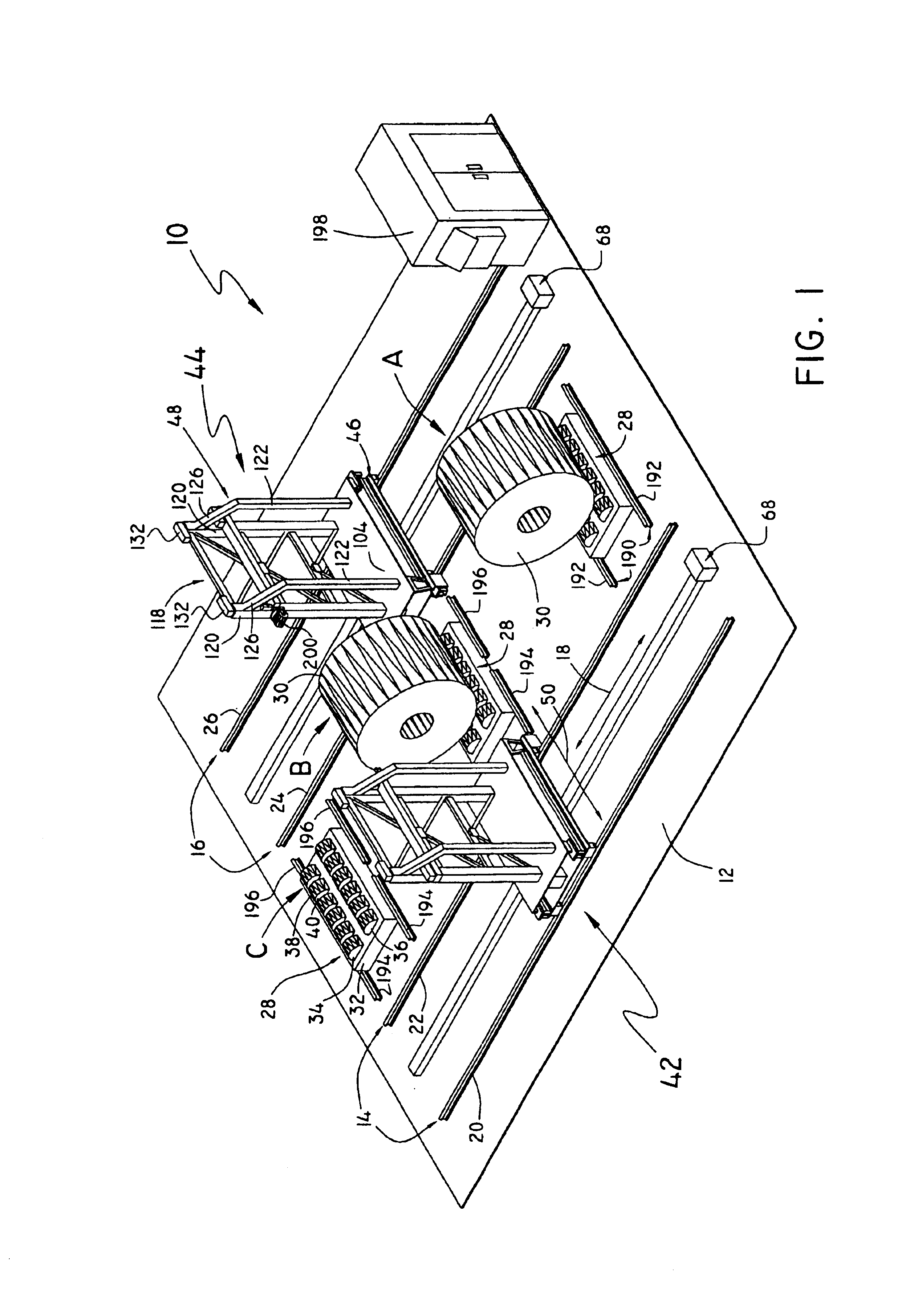
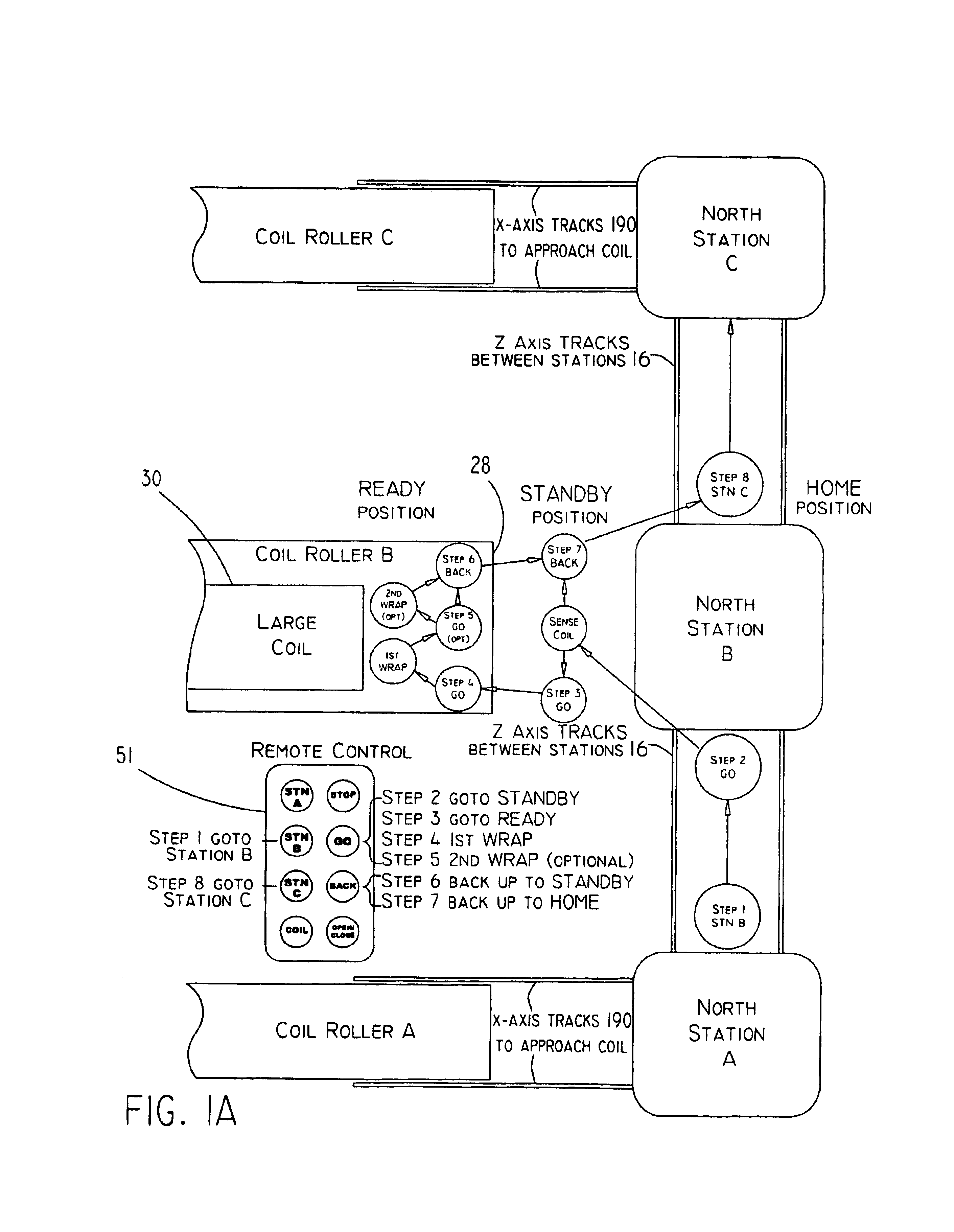
The inventive apparatus utilized in a coil wrapping production line 10 for performing the inventive method is shown schematically in FIG. 1. Fixed to the plant floor 12 is a pair of parallel tracks 14 and 16, extending in what shall herein be referred to as the Z-axis direction, shown by the double-ended arrow 18. Each of tracks 14 and 16 comprises a set of parallel rails 20, 22 and 24, 26, respectively. Spaced between tracks 14 and 16 and positioned transversely thereto are three work stations A, B, and C, also fixed to plant floor 12, each of which includes a coil roller 28 designed to support and rotate a large coil 30.

In order to avoid unduly crowding the drawing, only the coil roller 28 in station C will be given reference numerals. It is to be understood, however, that all such coil rollers 28 are essentially identical, and the same reference numerals apply to corresponding components in stations A and B. The frame for coil roller 28 includes a base 32 within which are journal...


PUM

PropertyMeasurementUnit
Timeaaaaaaaaaa
Pressureaaaaaaaaaa
Sizeaaaaaaaaaa

Abstract

This disclosure describes an apparatus for wrapping all exposed surfaces of a large annular coil, including its hollow cylindrical core, to prevent contamination and to prepare it for shipping. A pair of opposing robotic arms hand off or transfer a roll of wrapping material, such as paper or plastic, from a gripper on one arm to a gripper on the other arm. The arms travel around both ends of the coil, handing off the roll back and forth above the coil and in the center of its hollow core, as it is slowly rotated by a variable-speed coil roller. The speed of the coil roller is adjusted such that the wrap overlaps during each successive pass around the coil, thereby ensuring its sealed integrity. A compact variable-tensioning mechanism, inserted into the roll, maintains constant tension on the wrapping material to keep it taut while being pulled around the coil. The work envelope of the robotic arms traveling around the coil is adjusted to the relative height and width of each new coil to minimize wrap time and reduce wear and tear.

Description

1. Field of The InventionThis invention comprises an apparatus and method for wrapping an annular object. More specifically, it relates to wrapping and sealing off the exposed surfaces of a large coil of sheet metal, e.g., steel, aluminum, copper, etc., thereby preventing rust and other deteriorations over extended periods of time while in storage or in transit. Such rusting is prevented in the present illustrative embodiments by wrapping all exposed surfaces of the coil with stretch wrap, a material well known in the industry. The wrapped surfaces include inside the "eye" (or hollow cylindrical center core) of the coil, formed when the sheet metal is originally wound around a mandrel. Although disclosed in terms of sheet metal coils, the invention is applicable to other annular objects including but not limited to coils of paper, cables, wires, hoses, chains, etc. Also, although disclosed in terms of stretch wrap under tension, the invention is applicable to other wrapping material...

Claims


Application Information

Patent Timeline
IPC IPC(8): B65B25/00B65B25/24
CPCB65B25/24B65B11/04
Inventor MCGUINNESS, JAMESRHOADS, JAN E
Owner APPLIED TECH GROUP
Why Eureka
Try Eureka