
Noise reduction filter circuitry and method

a filter circuit and noise reduction technology, applied in the field of noise reduction filter circuitry, can solve the problems of image noise, major limiting factor of digital video, random arrival rate of incoming photons, etc., and achieve the effect of reducing noise and reducing noise in an input stream

Active Publication Date: 2014-07-08
ARM LTD
View PDF6 Cites 3 Cited by
  • Summary
  • Abstract
  • Description
  • Claims
  • Application Information

AI Technical Summary

Benefits of technology

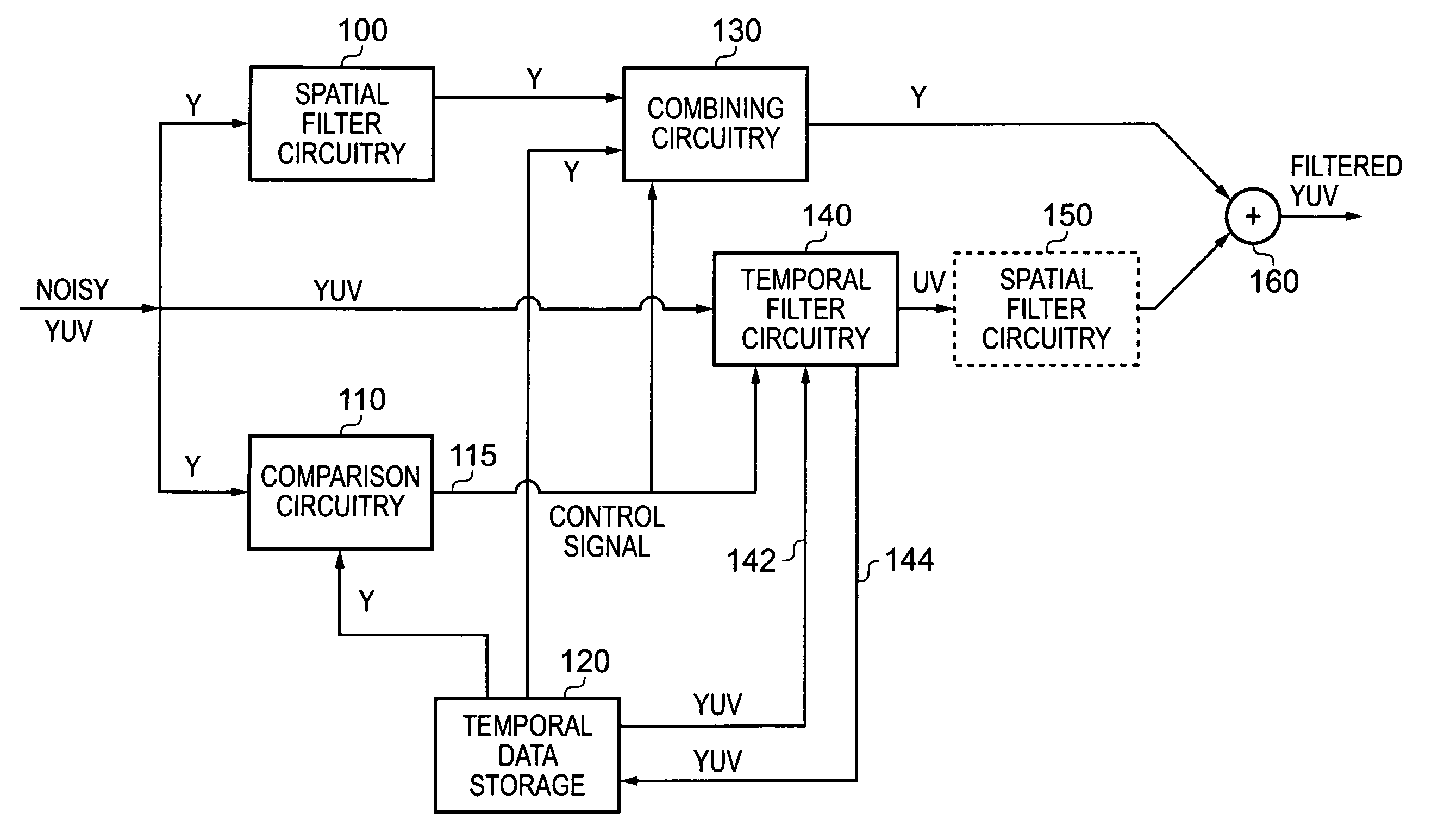
The present invention describes a filter circuit that reduces noise in a stream of image signals. The filter circuit includes a spatial filter that filters the image signals based on their luminance component. The filter circuit also includes comparison circuitry that compares the image signals with temporal data from multiple image signals. Based on this comparison, the filter circuit generates a control signal that determines the ratio of the output image signal between the spatially filtered signal and the temporal data. This control signal helps to reduce noise in the output image signal. The filter circuit is particularly effective when used in conjunction with encoding circuitry, as it significantly increases the efficiency of the encoder.

Problems solved by technology

Image noise is a problem dating back to the early days of photography.
The problem has since extended into the video domain, and is today a major limiting factor in digital video, both in terms of visual quality and compression performance.
The most obvious cause of image noise is the random arrival rate of incoming photons.
However, tougher constraints on size and weight, in combination with demand for video recording, limit the practical range of exposure time and aperture size.
However, digital image sensors are colour blind, in that they only count the number of incoming photons in a specific spot.
Images captured in such a manner suffer from noise associated with a variety of sources, the most common type of which is additive white Gaussian noise (AWGN).
Such a technique, also commonly known as demosaicing, distorts the noise distribution and presents a significant problem when dealing with noise detection.
In particular, the noise in adjacent pixels is no longer independent.
In particular, such noise can reduce the quality of the signal output by an encoder at a given bit rate, or increase the bit rate needed to achieve a given quality requirement, thereby reducing the amount of compression achieved.
Temporal filters generally allow for richer denoising possibilities but are more expensive to implement in terms of memory bandwidth, which is an important issue in embedded systems.
However, in video acquisition the exposure time is limited by the frame rate.
Unconstrained averaging on the other hand introduces motion blur that may be even more visually disturbing than the original noise.
As mentioned earlier, temporal filters are relatively expensive to implement in terms of memory bandwidth.
Whilst recursive filters of the type described by A Amer et al can offer benefits in this regard when compared with variable temporal depth filters, due to the need to access only a single previous frame (that representing the accumulated image) rather than multiple image frames, such recursive filters have traditionally had a significant disadvantage.
In particular, motion blur and noise cannot be simultaneously avoided in high movement areas even with a carefully designed motion adaptive control unit.

Method used


Image

  • Noise reduction filter circuitry and method
  • Noise reduction filter circuitry and method
  • Noise reduction filter circuitry and method

Examples


Embodiment Construction

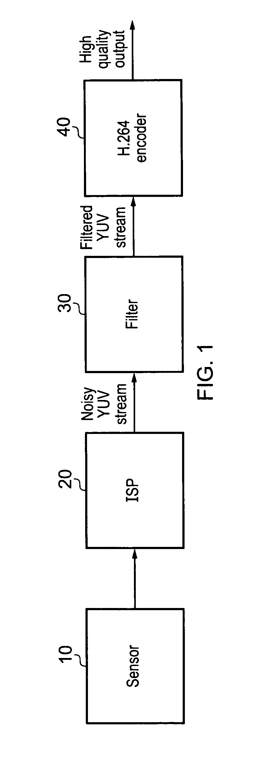
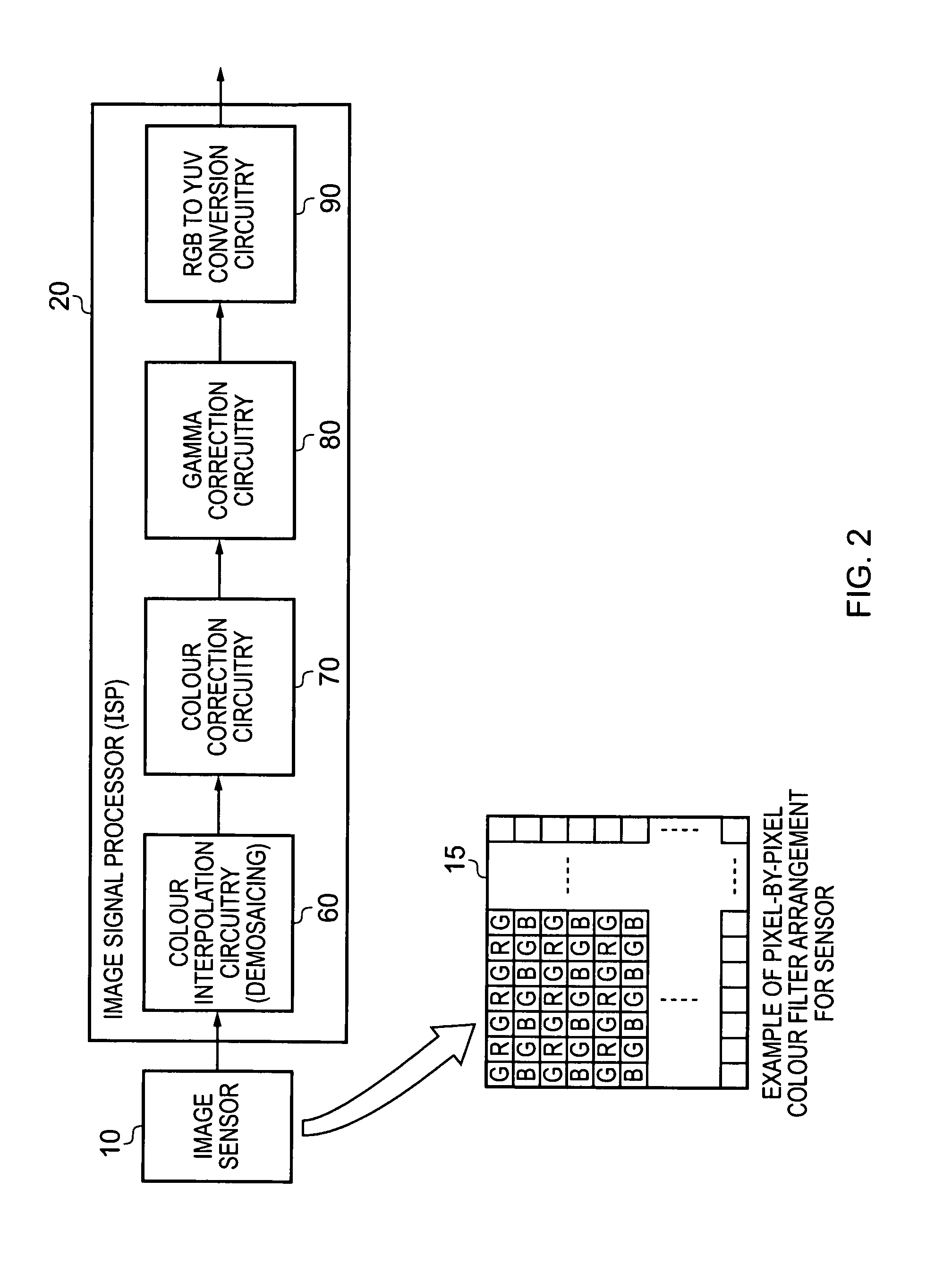
[0051]In accordance with an embodiment, a stream of YUV images is pre-filtered before being passed to a video encoder. FIG. 1 shows the intended application of the filter in accordance with such an embodiment. As shown in FIG. 1, a sequence of images forming a video signal are captured by a sensor 10, and are then subjected to some post-processing steps in an image signal processor (ISP) 20. In particular, the raw input data produced by the sensor is passed through several steps in an image pipeline within the ISP 20, resulting in the generation of an input stream of image signals in YUV format. This input stream of image signals suffers from noise introduced by the sensor 10, which is then typically modified and amplified by some of the functions performed within the ISP 20.

[0052]A filter 30 constructed in accordance with embodiments of the present invention is then used to produce a filtered stream of image signals in which the noise has been reduced, that filtered stream then bei...


PUM


Abstract

The present invention provides filter circuitry for reducing noise in an input stream of image signals having luminance and chrominance components. Spatial filter circuitry is provided which, for a current image signal of the input stream, generates a spatially filtered internal signal from at least the luminance component of the current image signal. Comparison circuitry is configured to compare the current image signal with temporal data derived from multiple image signals of the input stream, and to generate a control signal dependent on the comparison. Combining circuitry is then used to combine, in a ratio determined by the control signal, the spatially filtered internal signal with at least a luminance component derived from the temporal data, in order to generate at least the luminance component of a current output image signal that forms a noise reduced version of the current image signal. Such a form of filter circuitry has been found to provide a filtered stream of image signals with significant noise suppression, and is particularly well suited to providing a filtered stream of image signals for input to video encoding circuitry, enabling significant improvements in the efficiency of the encoding circuitry by virtue of the manner in which the noise is suppressed.

Description

BACKGROUND OF THE INVENTION[0001]1. Field of the Invention[0002]The present invention relates to noise reduction filter circuitry, and to a method of operation of such filter circuitry. In particular, the present invention relates to filter circuitry for reducing noise in an input stream of image signals forming a video stream, and is suitable for use prior to input to a video encoder used to compress the video stream.[0003]2. Description of the Prior Art[0004]Image noise is a problem dating back to the early days of photography. The problem has since extended into the video domain, and is today a major limiting factor in digital video, both in terms of visual quality and compression performance.[0005]The most obvious cause of image noise is the random arrival rate of incoming photons. This noise cannot be eliminated, but it can be reduced to acceptable levels by increasing the number of photons per pixel, effectively reducing the variance around the true pixel value. The traditiona...

Claims


Application Information

Patent Timeline
Patent Type & Authority Patents(United States)
IPC IPC(8): H04N5/21
CPCH04N5/21H04N9/646H04N9/77
Inventor PERSSON, ERIKEDGREN, PER
Owner ARM LTD
Learn More