
Artificial turf remover and infill separator, and method of use thereof

a technology of infill separator and remover, which is applied in the direction of cleaning using liquids, cleaning with photosensitive materials, and ways, etc., can solve the problems of poor base drainage, insufficient infill material removal efficiency, so as to efficiently comb infill and efficiently loose any infill material

Inactive Publication Date: 2014-07-08
MITCHELL MARK
View PDF25 Cites 10 Cited by
  • Summary
  • Abstract
  • Description
  • Claims
  • Application Information

AI Technical Summary

Benefits of technology

Efficiently removes infill material from artificial turf by inverting it and using various mechanisms to dislodge and collect the material, allowing for effective separation and collection, and the ability to roll the turf into a cylindrical shape for storage.

Problems solved by technology

The reasons for replacing artificial turf may be because the artificial turf is worn out, or because the artificial turf has been installed inappropriately, for example, base drainage is poor.
However, while such a device utilizes grinder structures with rounded bars to remove infill material, it does not invert the turf to remove infill material, and thus does not efficiently remove all the infill material.
While such a device is useful in removing infill from artificial turf, it utilizes only fin-shaped prongs to dislodge the infill material and does not turn the turf upside down to remove the infill material, and thus does not efficiently remove all the infill material.
However, while such a device utilizes beater bars to remove infill material, it does not invert the turf to comb infill from the artificial turf, and thus does not efficiently remove all the infill material.

Method used


Image

  • Artificial turf remover and infill separator, and method of use thereof
  • Artificial turf remover and infill separator, and method of use thereof
  • Artificial turf remover and infill separator, and method of use thereof

Examples


Embodiment Construction

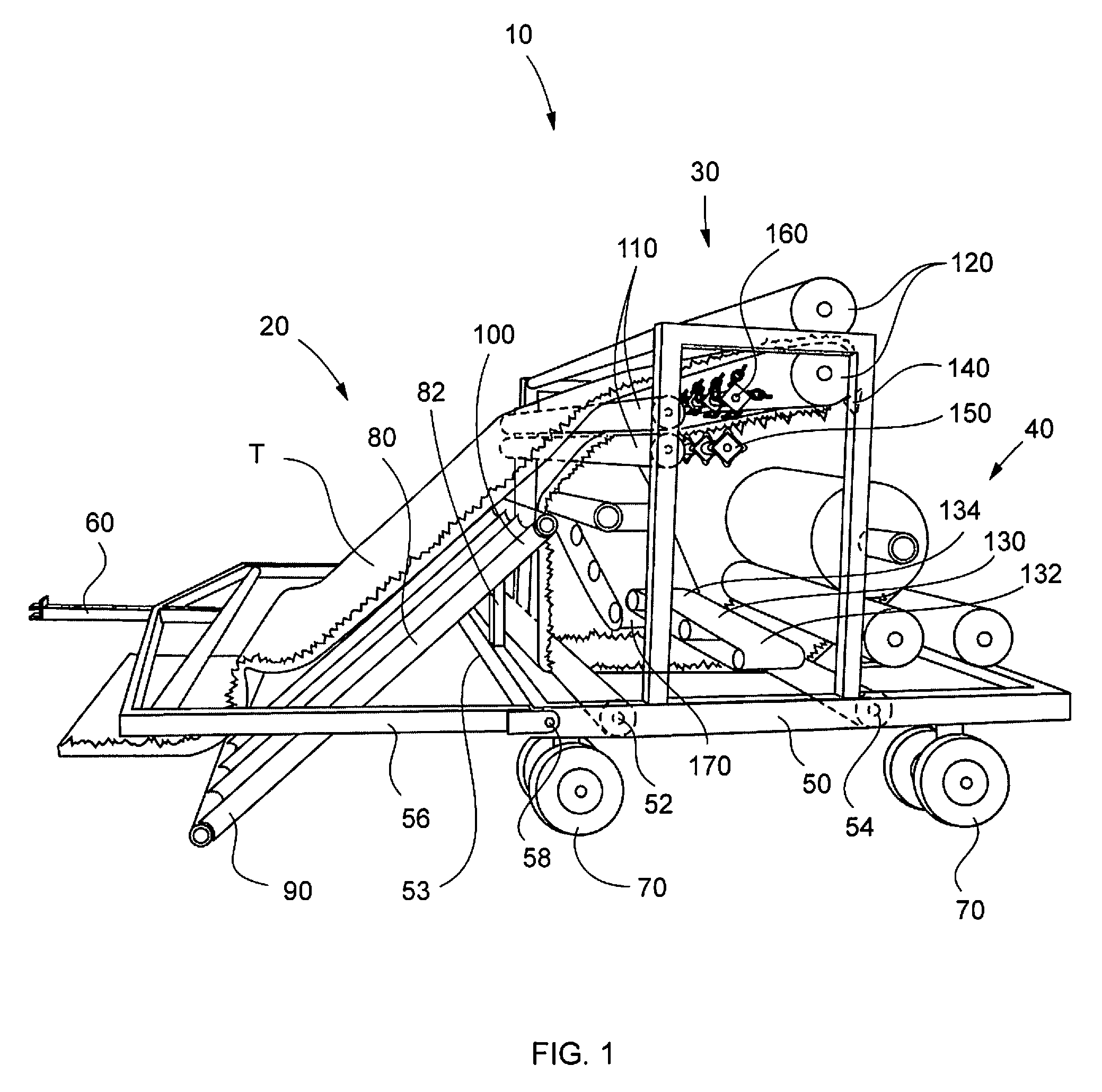
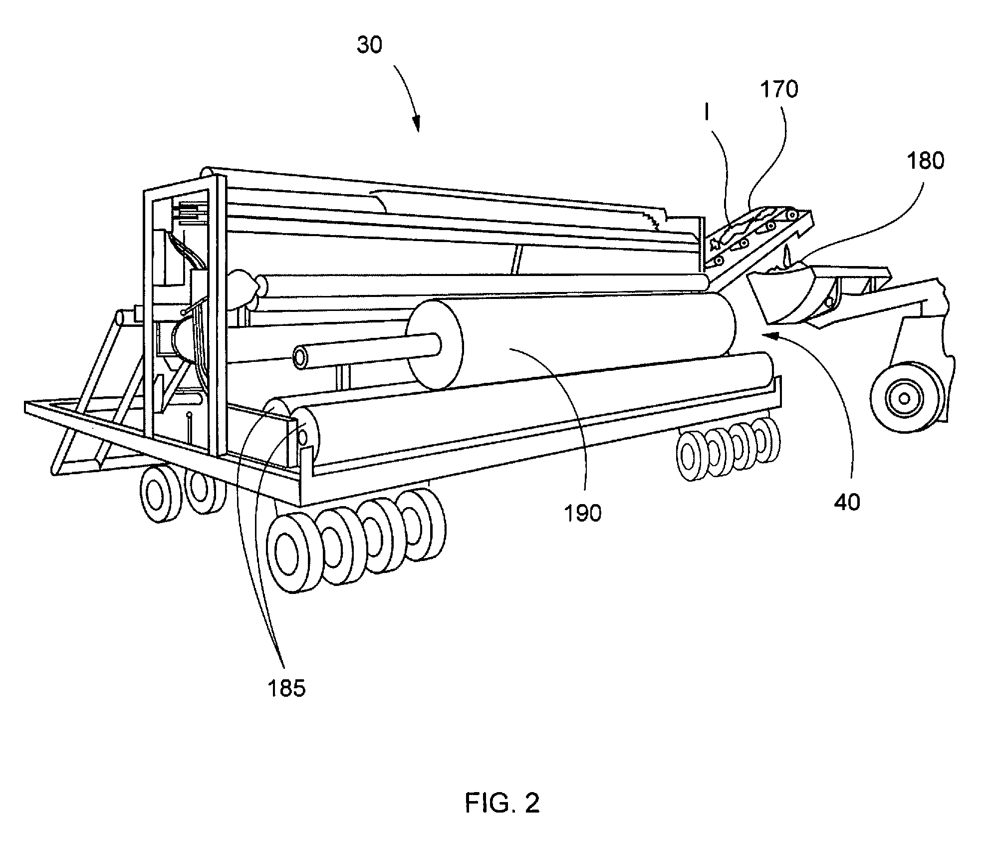
[0057]In describing the preferred and selected alternate embodiments of the present invention, as illustrated in FIGS. 1-12, specific terminology is employed for the sake of clarity. The invention, however, is not intended to be limited to the specific terminology so selected, and it is to be understood that each specific element includes all technical equivalents that operate in a similar manner to accomplish similar functions.

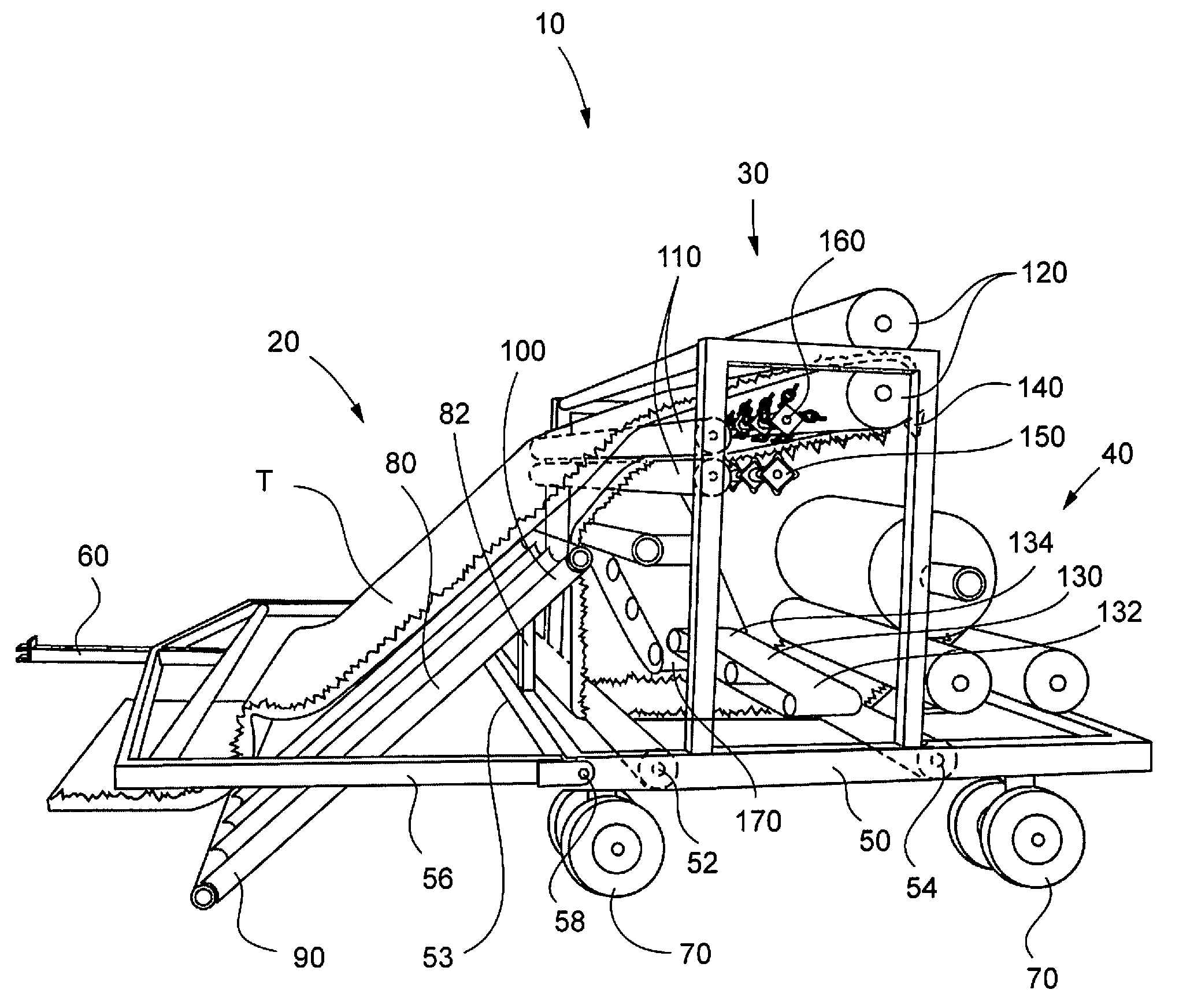
[0058]Referring now to FIG. 1, artificial turf remover and infill separator 10 comprises artificial turf removing station 20, infill separating station 30 and artificial turf collection station 40, wherein artificial turf removing station 20, infill separating station 30 and artificial turf collection station 40 are disposed on base frame 50, and wherein base frame 50 comprises first base roller 52, front edge 53, second base roller 54 and wheels 70. Collapsible front frame 56 is hingably secured to front edge 53 of base frame 50, wherein collapsible front fr...


PUM

PropertyMeasurementUnit
gravitational forceaaaaaaaaaa
rotationaaaaaaaaaa
cylindrical shapeaaaaaaaaaa

Abstract

An artificial turf remover and infill separator comprising an artificial turf removing station, an infill separating station and an artificial turf collection station. The infill separating station comprises rotatable spinning devices comprises corners, wherein each corner comprises chain links. The artificial turf remover and infill separator is utilized by positioning a strip of artificial turf on an angular ramp, conveying the artificial turf over a first pair of rotatable rollers, conveying the artificial turf between a second pair of rotatable rollers, separating infill from the artificial turf via fin-shaped picks, square-shaped rotatable diggers and the rotatable spinning devices, wherein the chain links jostle the infill material from the artificial turf onto a first and second infill collection conveyor belt. The artificial turf is then conveyed over a first and second base roller, between a rear pair of counter-rotating rollers and then wound around a final artificial turf collection roller.

Description

CROSS-REFERENCE TO RELATED APPLICATIONSNoneFEDERALLY SPONSORED RESEARCH OR DEVELOPMENTNonePARTIES TO A JOINT RESEARCH AGREEMENTNoneREFERENCE TO A SEQUENCE LISTINGNoneBACKGROUND OF THE INVENTION[0001]1. Technical Field of the Invention[0002]The preferred embodiment relates generally to an artificial turf remover and infill separator, and method of use thereof, and more specifically to an artificial turf remover and infill separator comprising an artificial turf removing station, an infill separating station and an artificial turf collecting station. The infill separating station comprises fin-shaped picks and rotatable diggers that remove infill from the face of the artificial turf as it is turned upside down. Additionally, the infill separating station comprises rotatable spinning devices having chain links secured thereto, that whip against collected artificial turf to jostle loose the infill material.[0003]2. Description of Related Art[0004]Artificial turf is commonly utilized on ...

Claims


Application Information

Patent Timeline
Patent Type & Authority Patents(United States)
IPC IPC(8): B21B45/02
CPCE01C13/08A63C19/12A01G20/12
Inventor MITCHELL, MARK
Owner MITCHELL MARK
Learn More