
Propeller arrangement

a technology of propellers and assemblies, applied in the direction of rotors, marine propulsion, vessel construction, etc., can solve the problems of increased noise generation, increased noise generation of contra-rotating propellers, and general increase in noise generation of single propeller assembly arrangements, so as to reduce the radial displacement of propellers, reduce actuation distances, and facilitate the effect of accommodation

Active Publication Date: 2014-07-08
ROLLS ROYCE PLC
View PDF13 Cites 1 Cited by
  • Summary
  • Abstract
  • Description
  • Claims
  • Application Information

AI Technical Summary

Benefits of technology

The solution minimizes noise generation and maintains propulsive efficiency by ensuring the second propeller tips do not interact with vortices, achieving a desired radial offset through small, opposing radial movements, which reduces the complexity and size of the control system components.

Problems solved by technology

However, such arrangements, known in the art as contra-rotating propellers, generally suffer from increased noise generation compared to single propeller assembly arrangements.
If the diameter of the second propeller assembly is larger than the diameter of the stream tube then noise generation will increase as the second row of propellers chop through the vortices.

Method used


Image

  • Propeller arrangement
  • Propeller arrangement

Examples


Embodiment Construction

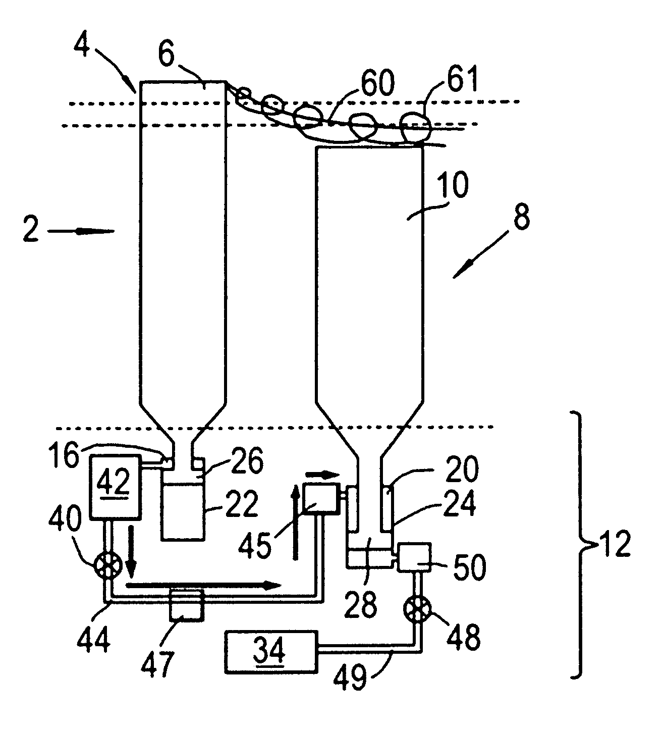
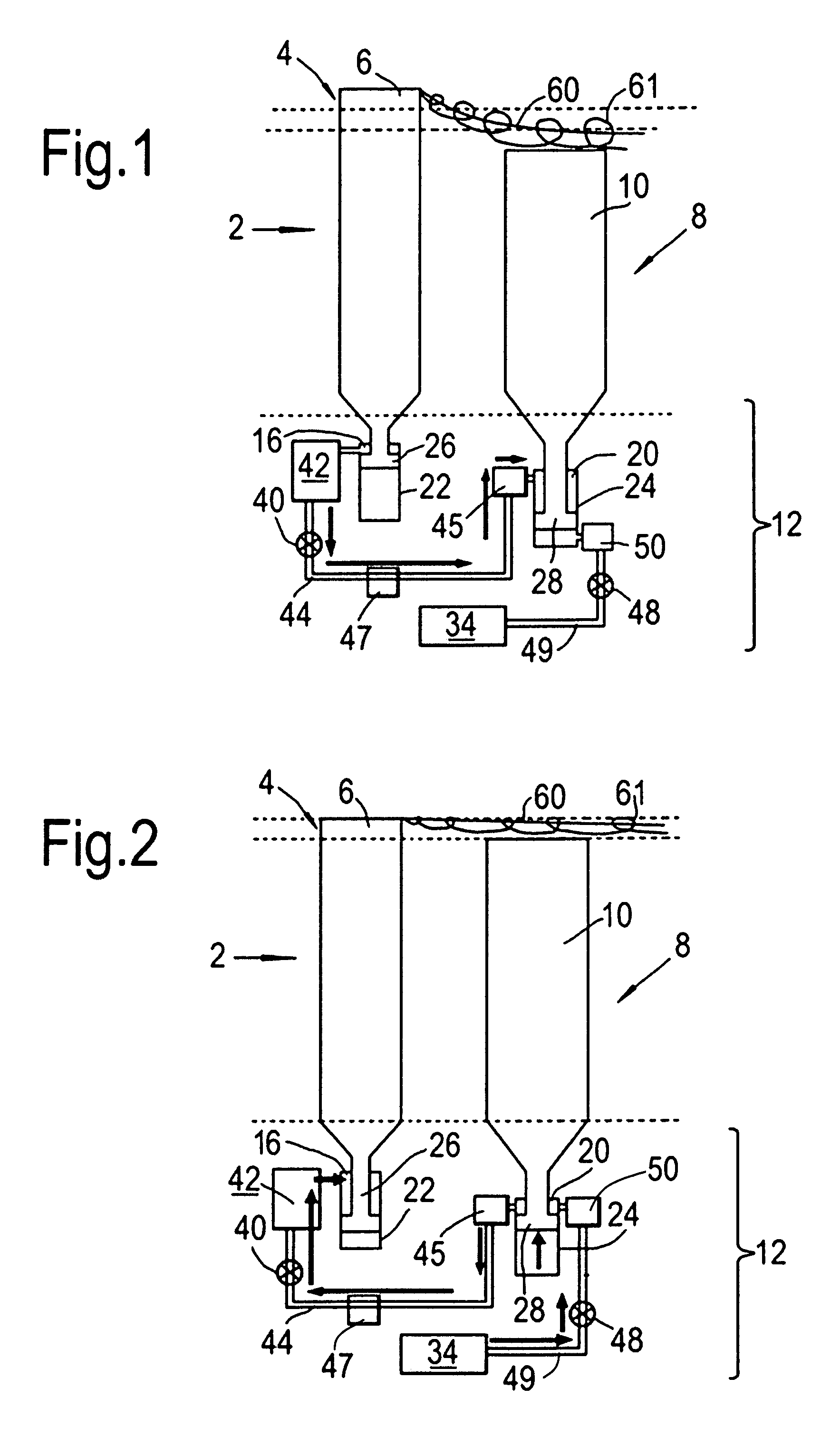
[0045]FIG. 1 shows a schematic longitudinal cross-section through a propeller arrangement 2 having a first propeller assembly 4 providing a row of first propellers 6 and a second propeller assembly 8 providing a row of contra-rotating second propellers 10, the propellers of both assemblies being extendable and retractable in a radial direction. The degree of extension or retraction of the propellers is controlled by a control system 12 which comprises first 22 and second 24 hydraulic cylinders and first 26 and second 28 pistons which are movable in the respective cylinders. The pistons are conveniently formed by the respective roots of the first and the second propellers. Each first cylinder and first piston pair forms a first hydraulic chamber 16, and each second cylinder and second piston pair forms a second hydraulic chamber 20, the fluid in the chambers being pressurised by radially outward movement of the pistons.

[0046]The control system 12 allows the first 16 and second 20 cha...


PUM


Abstract

A propeller arrangement has a first propeller assembly providing a row of first propellers, and a second propeller assembly, rearward of the first propeller assembly, providing a row of second propellers. The first and second propellers are radially extendable and retractable. The propeller arrangement further has a control system for controlling the extension and retraction of the first and second propellers. The control system is arranged such that when the propellers of one of the first and second propeller assemblies extend, the propellers of the other of the first and second assemblies retract.

Description

FIELD OF THE INVENTION[0001]The present invention relates to a propeller arrangement, particularly a variable diameter propeller arrangement.BACKGROUND OF THE INVENTION[0002]A purpose of a propeller is to convert the rotary motion of an engine into propulsive force, or thrust.[0003]Increasingly, the design of modern propeller arrangements is influenced by environmental considerations. Such considerations include a need for increased fuel efficiency and reduced noise generation.[0004]It is known that the efficiency of a traditional single-propeller assembly is increased by the provision of a second propeller assembly rotating in an opposite direction downstream of the first propeller. However, such arrangements, known in the art as contra-rotating propellers, generally suffer from increased noise generation compared to single propeller assembly arrangements.[0005]It is understood that the increased noise generation is partly due to stream tube contraction and interaction between the ...

Claims


Application Information

Patent Timeline
Patent Type & Authority Patents(United States)
IPC IPC(8): F01D1/24
CPCB64C11/003B64C11/48B64D2027/026B64D27/026
Inventor LAVRENKO, ALEXANDER, V.
Owner ROLLS ROYCE PLC
Learn More