
Ultra wideband radio frequency identification system, method, and apparatus

a radio frequency identification and ultra wideband technology, applied in the field of ultra wideband radio frequency identification systems, methods, and apparatus, can solve the problems of prohibitively expensive for widespread use on individual items of small value, limited read-write operating range, and many limitations of current rfid tags that use standard wave-oriented communication technologies, etc., to achieve simple electronics, reduce costs, and prolong battery life

Inactive Publication Date: 2014-07-01
LIGHTWAVES SYST
View PDF118 Cites 5 Cited by
  • Summary
  • Abstract
  • Description
  • Claims
  • Application Information

AI Technical Summary

Benefits of technology

The present invention is a system that uses ultra wideband (UWB) technology to transmit and store data wirelessly. The invention offers advantages such as simpler electronics, longer battery life, and longer operating ranges. It also uses a protocol for pulse-based communications and a Common Platform for simultaneous transmission of streaming and non-streaming data. The invention provides a secure, high-speed, and universal data interchange solution.

Problems solved by technology

Current RFID tags that use standard wave-oriented communication technologies have many limitations.
Either, they are extremely limited in their read-write operating range (typically less than 30 ft), or when designed with an extended operating range (several hundred feet) they are prohibitively expensive for widespread use on individual items of small value.
Also, RFID tags built on standard wave-oriented communication technologies are limited by multi-path signal cancellation, anti-collision algorithms, and battery life issues.
To date, RFID products for these, and other applications, are based on wave-oriented communications, which are fundamentally limited by the physics of continuously oscillating radio frequency technology.
However, current UWB RFID products aren't used to store data in a structured or partitioned manner like their wave-oriented RFID counterparts.
Active tags can be read from 300 feet (100 meters) or more, but they're expensive (typically more than U.S.$20 each).
Chipless tags that use embedded fibers have one drawback for supply chain uses—only one tag can be read at a time.
When UHF antenna is close to metal or metallic material, the antenna can be detuned, resulting in poor performance.
Cells phones, wireless computers and even robots in factories can produce radio waves that interfere with RFID tags.
The UHF bands in Europe and Japan are much smaller so this technique is not effective for preventing reader interference.
But they consume more power than low-frequency tags.
The main disadvantages of low-frequency tags are they have to be read from within three feet and the rate of data transfer is slow.
They have very high transfer rates and can be read from as far as 30 feet away, but they use a lot of power and are expensive.
Noise can be caused by other RF devices, robots, electric motors and other machines.
But there are chipless forms of RFID tags that use material to reflect back a portion of the radio waves beamed at them.
Read-write tags are more expensive than read-only tags.
Water absorbs UHF energy, causing signal attenuation.
UHF tags are also more expensive than low-frequency tags, and they use more power.

Method used


Image

  • Ultra wideband radio frequency identification system, method, and apparatus
  • Ultra wideband radio frequency identification system, method, and apparatus
  • Ultra wideband radio frequency identification system, method, and apparatus

Examples


Embodiment Construction

)

[0292]A preferred embodiment of the present invention will be described as it applies to its preferred embodiment. It is not intended that the present invention be limited to the described embodiment. It is intended that the invention cover all modifications and alternatives which may be included within the spirit and scope of the invention.

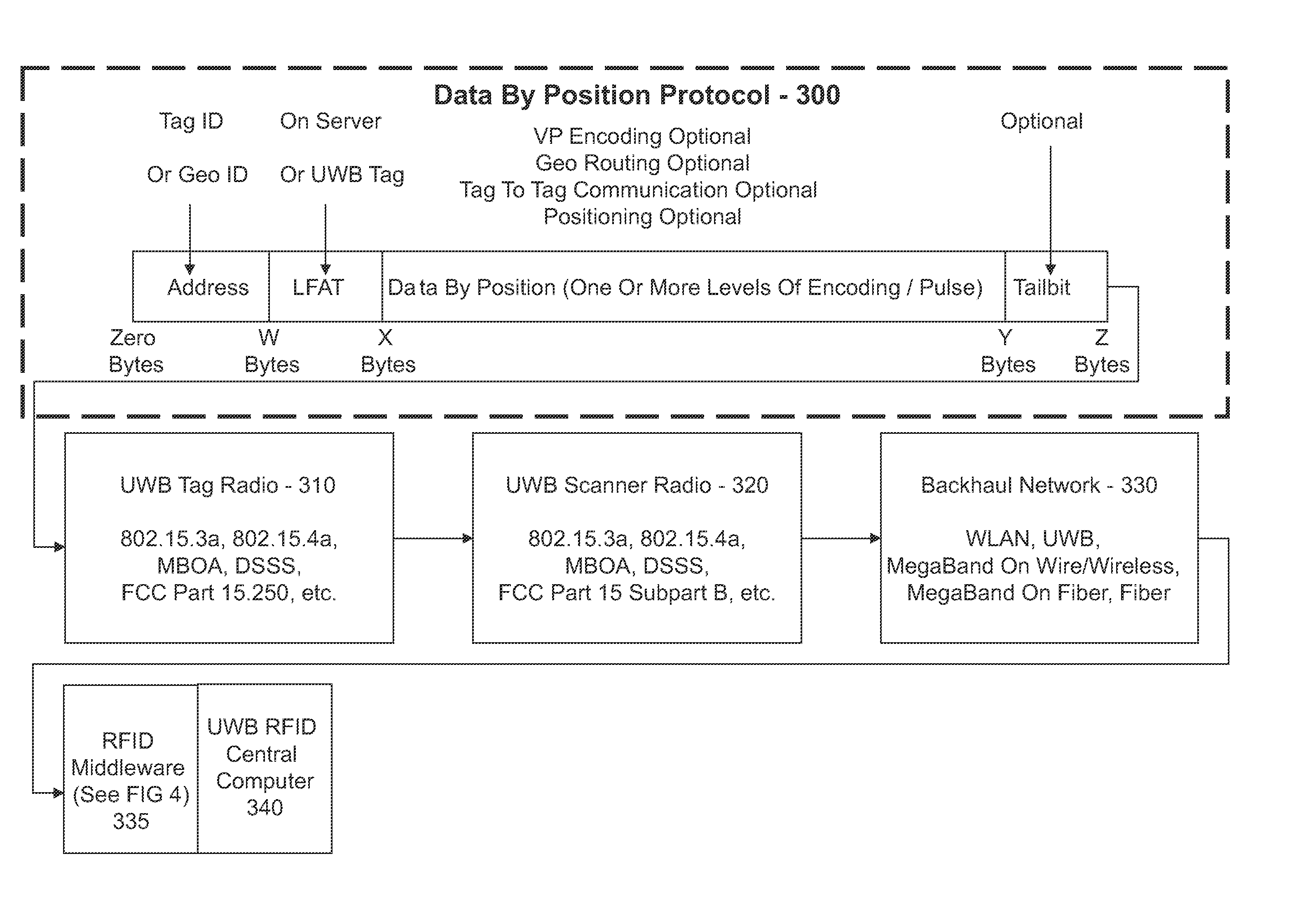
[0293]A feature of the present invention is a UWB pulse-based structured linear database which provides a common platform for the transmission and receipt of RFID partitioned data. The reigning standard for wave-oriented RFID is the Electronic Product Code (EPC) standard. The following comes from an EPC document entitled The EPC Global Architecture Framework, page 11, line 296-305, “For trading partners to exchange information, they must have prior agreement as to the structure and meaning of data to be exchanged, and the mechanisms by which exchange will be carried out. EPCglobal standards include data standards and information exchange standar...


PUM


Abstract

A method associated with a UWB RFID system provides for receiving a data transmission transmitted using UWB and accessing data within the data transmission using a communications protocol. An initial portion of the data transmission defines a structure of the data transmission such that subsequent data in the data transmission is directly accessible without additional decoding.

Description

CROSS-REFERENCE TO RELATED APPLICATIONS[0001]This application is a conversion of and claims priority to U.S Provisional Patent Application Ser. No. 60 / 795,235, entitled Ultra Wideband Radio Frequency Identification System, Method, and Apparatus, filed on Apr. 26, 2006.[0002]This application is also a continuation-in-part of and claims priority to U.S. patent application Ser. No. 11 / 622,824, entitled Globally Referenced Positioning in a Shielded Environment, filed on Jan. 12, 2007, now U.S. Pat. No. 7,340,283 issued on Mar. 4, 2008.[0003]This application is also a continuation-in-part of and claims priority to U.S. patent application Ser. No. 10 / 427,039, entitled High Bandwidth Data Transport System, filed on Apr. 30, 2003, now U.S. Pat. No. 7,376,191 issued on May 20, 2008.[0004]This application is also a continuation-in-part of U.S. patent application Ser. No. 10 / 967,850, entitled Improved High Bandwidth Data Transport System, filed on Oct. 18, 2004, now U.S. Pat. No. 7,986,729 iss...

Claims


Application Information

Patent Timeline
Patent Type & Authority Patents(United States)
IPC IPC(8): H04Q5/22
CPCH04W99/00G06K7/10306
Inventor KENNEDY, PHILIP T.GERKE, JOSEPH A.SNYDER, DAVID M.BAYCH, LESLIE D.MELICK, BRUCE D.
Owner LIGHTWAVES SYST
Learn More