Ultrasonic probe and ultrasonic imaging apparatus
an ultrasonic probe and ultrasonic imaging technology, applied in the field of ultrasonic probes and ultrasonic imaging devices, can solve the problems of increasing the risk of erroneous diagnosis and inspection, undesired signals, etc., and achieve the effect of preventing artifacts and suppressing undesired response components
- Summary
- Abstract
- Description
- Claims
- Application Information
AI Technical Summary
Benefits of technology
Problems solved by technology
Method used
Image


Examples
first embodiment
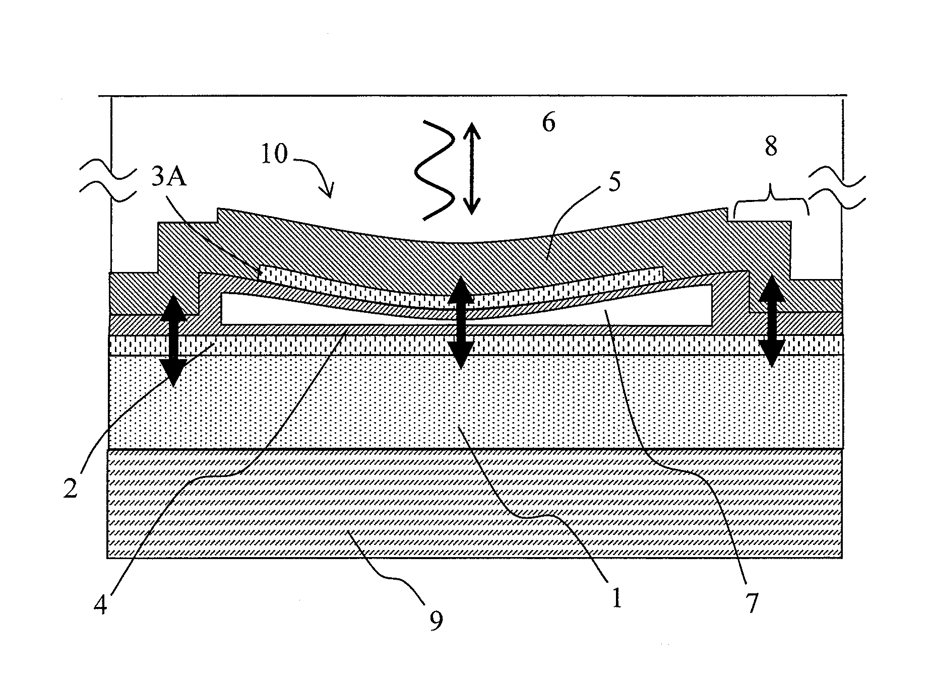
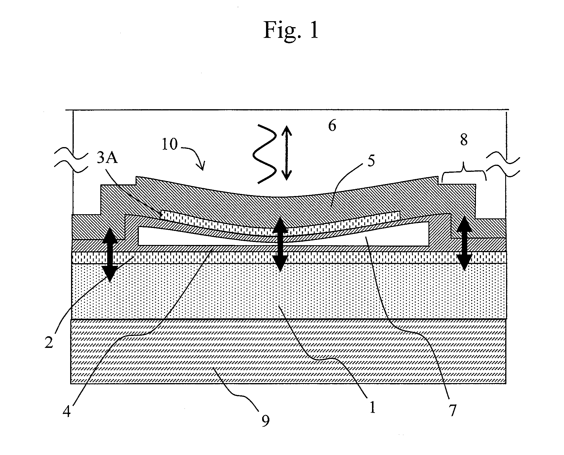
[0040]FIG. 1 is a vertical cross sectional view of a first embodiment of CMUT (10), and FIG. 2 is a plan view thereof. The A-A section in FIG. 2 corresponds to FIG. 1. FIG. 2 indicates the top of the plane 3A of FIG. 1. It is noted that for the sake of convenience of description, the direction in which the CMUT (10) transmits ultrasonic wave, that is, upward in FIG. 1 and a vertically upward direction with respect to the plane of the page of FIG. 2 are supposed to be a z direction. Moreover, the right hand directions of FIGS. 1 and 2 are supposed to be an x direction, and vertically downward direction with respect to the plane of the page of FIG. 1 and the upward direction of FIG. 2 are supposed to be a y direction.
[0041]As shown in FIGS. 1 and 2, the CMUT (10) is configured such that a thin-film like lower electrode 2 made up of a conductor such as aluminum and tungsten is formed on a planar substrate 1 made up of an insulator or semiconductor such as a silicon single crystal, and ...
second embodiment
[0073]The description of the first embodiment has supposed that the medium is an acoustic lens (sound velocity=1000 m / s). However, in actual use situations, there are cases where the CMUT is in direct contact with water and a living body 12 as shown in FIG. 13. It is noted that the structure of vibrating portion of CMUT is omitted from illustration in FIG. 13. Water and a living body have a longitudinal-wave sound velocity of about 1500 [m / s]. Since the coincidence frequency is determined from the lateral-wave sound velocity of the substrate 1 and the sound velocity of the material in contact with the substrate, an optimum substrate thickness will vary when the material in contact is changed.
[0074]FIG. 14 shows a curve 110 of relation between the coincidence frequency and the substrate thickness when supposing that the medium in contact with the substrate is water (sound velocity is 1500 [m / s]). Supposing that a CMUT has a cut-off frequency at 3 [MHz] and the medium is water, when t...
third embodiment
[0075]In the above described two embodiments, it is supposed that in the medium, the energy of lateral wave is radiated toward the upper side (+z side) of CMUT. The use method of ultrasonic probe includes a case in which a backing material 13 is bonded to the underside (−z side) as shown in FIG. 13. It is often the case that a resin or metal having a sound velocity of 2000 to 3000 [m / s] is used as the backing material. As in the second embodiment, since the coincidence frequency is determined from the lateral-wave sound velocity of the substrate 1 and the sound velocity of the material in contact, an optimum substrate thickness will vary when the material in contact is changed.
[0076]FIG. 15 shows a curve 120 of relation between the coincidence frequency and the substrate thickness when supposing that the medium into which acoustic energy is radiated is a backing material (sound velocity=2500 [m / s]). The substrate thickness when the coincidence frequency is set at 3 [MHz] will be abo...
PUM
 Abstract
Description
Claims
Application Information
 - R&D
- Intellectual Property
- Life Sciences
- Materials
- Tech Scout
- Unparalleled Data Quality
- Higher Quality Content
- 60% Fewer Hallucinations
Browse by: Latest US Patents, China's latest patents, Technical Efficacy Thesaurus, Application Domain, Technology Topic, Popular Technical Reports.
© 2025 PatSnap. All rights reserved.Legal|Privacy policy|Modern Slavery Act Transparency Statement|Sitemap|About US| Contact US: help@patsnap.com