
Apparatus and method for capacitors having engineered electrodes with very high energy density

a capacitor and energy density technology, applied in the field of electric charge storage devices and methods, can solve the problems of reducing retention time, no known good solution to the general problem of energy storage, and time to lose 10% of stored energy

Inactive Publication Date: 2014-06-24
GRANBLUETECH L L C
View PDF4 Cites 13 Cited by
  • Summary
  • Abstract
  • Description
  • Claims
  • Application Information

AI Technical Summary

Benefits of technology

This patent is about a special type of energy storage device called a capacitor. The capacitor has two electrically conducting electrodes separated by a non-conductive region. The non-conductive region has a specific permittivity value that affects its performance. The patent will be useful for a variety of applications, such as electric vehicles, power supplies, wind turbines, and more, that require wide temperature ranges and extreme temperature conditions. The patent aims to improve the performance and reliability of such capacitors in extreme temperature environments.

Problems solved by technology

At the present time there is no known good solution to the general problem of energy storage.
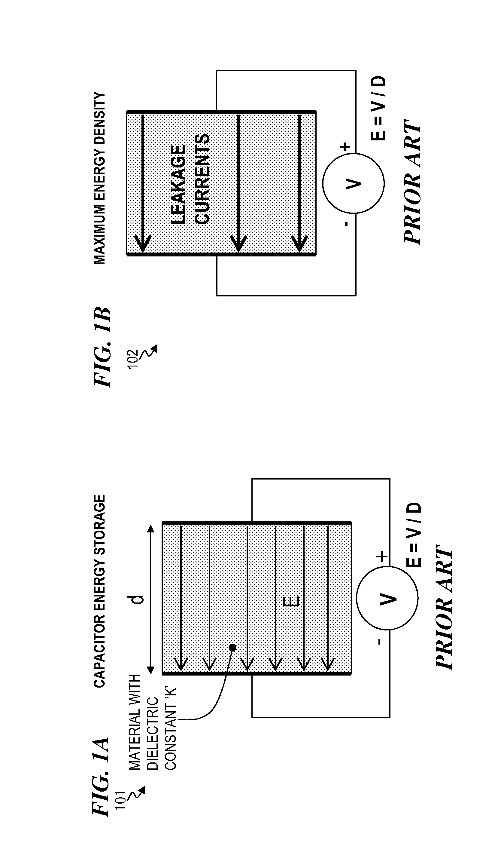
Increased leakage currents lead to reduced retention time (e.g., time to lose 10% of stored energy).
Thus there is a tradeoff between energy density and retention time.

Method used


Image

  • Apparatus and method for capacitors having engineered electrodes with very high energy density
  • Apparatus and method for capacitors having engineered electrodes with very high energy density
  • Apparatus and method for capacitors having engineered electrodes with very high energy density

Examples


Embodiment Construction

[0041]Although the following detailed description contains many specifics for the purpose of illustration, a person of ordinary skill in the art will appreciate that many variations and alterations to the following details are within the scope of the invention. Accordingly, the following preferred embodiments of the invention are set forth without any loss of generality to, and without imposing limitations upon the claimed invention. Further, in the following detailed description of the preferred embodiments, reference is made to the accompanying drawings that form a part hereof, and in which are shown by way of illustration specific embodiments in which the invention may be practiced. It is understood that other embodiments may be utilized and structural changes may be made without departing from the scope of the present invention.

[0042]The leading digit(s) of reference numbers appearing in the Figures generally corresponds to the Figure number in which that component is first intr...


PUM

PropertyMeasurementUnit
dielectric constantsaaaaaaaaaa
energy densityaaaaaaaaaa

Abstract

An apparatus and associated method for an energy-storage device (e.g., a capacitor) having a plurality of electrically conducting electrodes including a first electrode and a second electrode separated by a non-electrically conducting region, and wherein the non-electrically conducting region further includes a non-uniform permittivity (K) value. In some embodiments, the method includes providing a substrate; fabricating a first electrode on the substrate; and fabricating a second electrode such that the second electrode is separated from the first electrode by a non-electrically conducting region, wherein the non-electrically conducting region has a non-uniform permittivity (K) value. The capacitor devices will find benefit for use in electric vehicles, of all kinds, uninterruptible power supplies, wind turbines, mobile phones, and the like requiring wide temperature ranges from several hundreds of degrees C. down to absolute zero, consumer electronics operating in a temperature range of −55 degrees C. to 125 degrees C.

Description

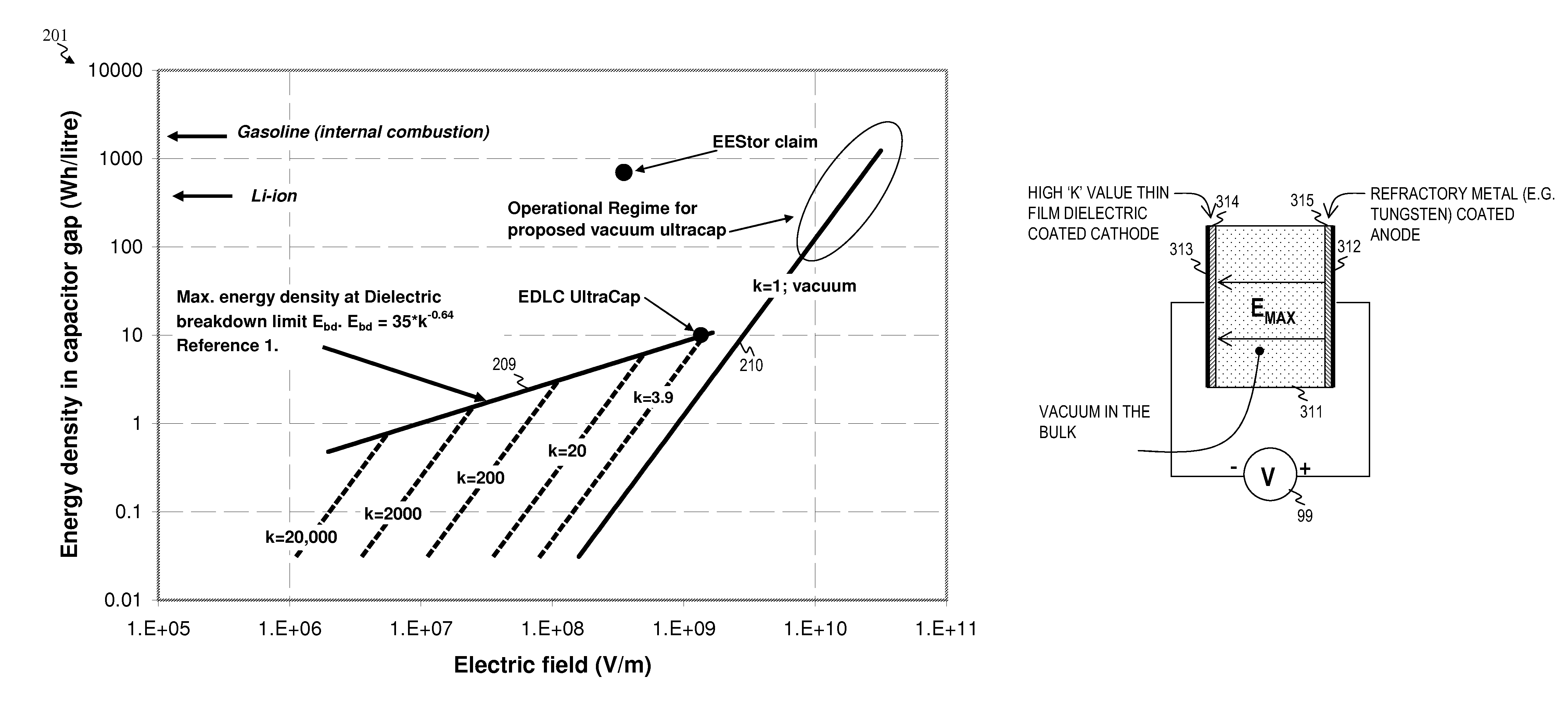
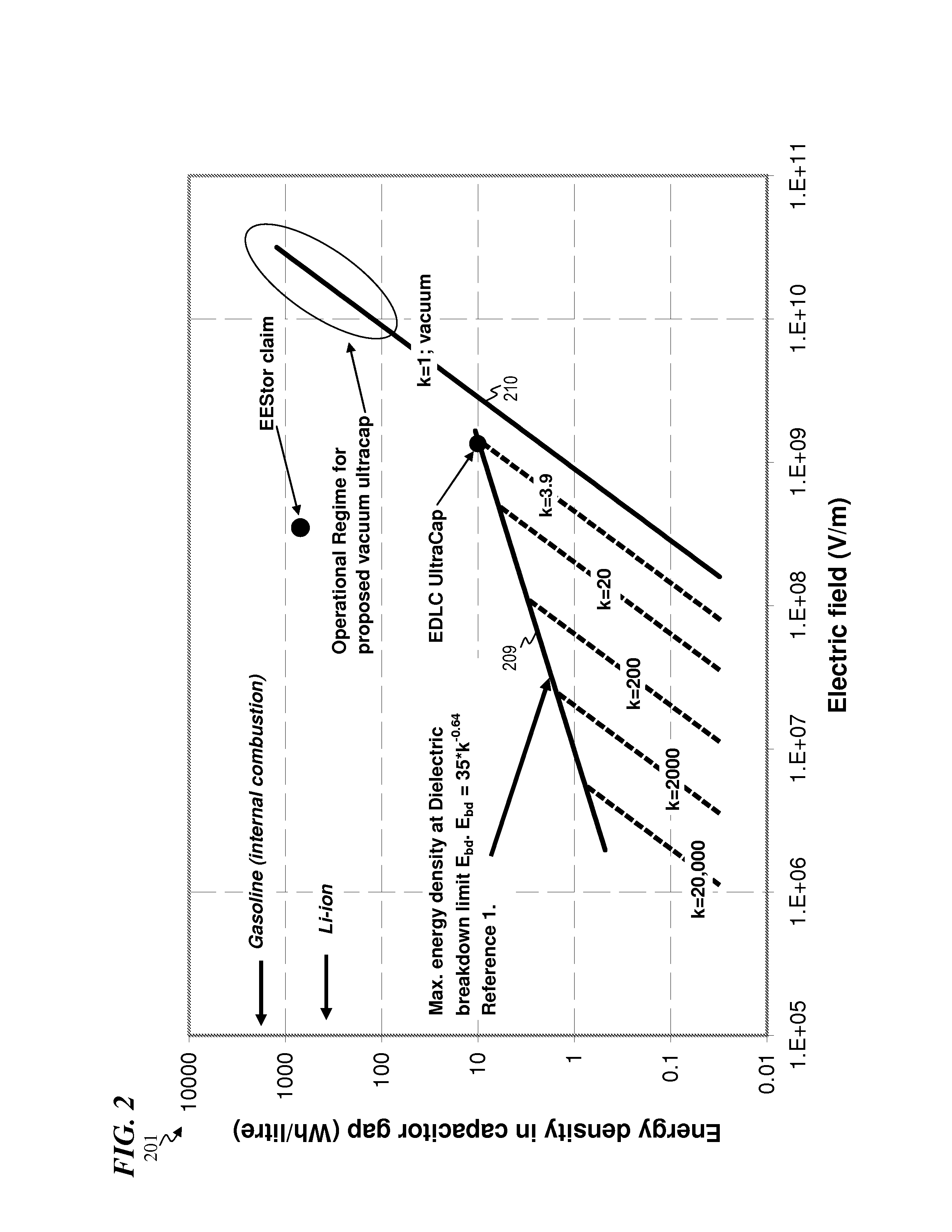
CROSS-REFERENCE TO RELATED APPLICATIONS[0001]This application claims priority benefit under 35 U.S.C. §119(e) to: U.S. Provisional Patent Application No. 61 / 325,173 filed Apr. 16, 2010, by John P. Snyder, titled “APPARATUS AND METHOD FOR A CAPACITOR WITH ENGINEERED ELECTRODES AND POSITION DEPENDENT PERMITTIVITY FOR VERY HIGH ENERGY DENSITY”;which is incorporated herein by reference in its entirety.FIELD OF THE INVENTION[0002]The present invention relates to electrical-charge-storage devices and methods, and more particularly to apparatus and methods for capacitor devices having engineered electrodes and position dependent permittivity for providing very high energy densities.BACKGROUND OF THE INVENTION[0003]At the present time there is no known good solution to the general problem of energy storage. A good solution is one that needs to have as many of the following characteristics as possible:[0004]1) High energy density per volume and per mass[0005]2) Low cost of manufacture[0006]3...

Claims


Application Information

Patent Timeline
Patent Type & Authority Patents(United States)
IPC IPC(8): H01G4/02H01G9/00H10N97/00
CPCH01G11/86H01G9/00H01L28/40H01G11/26H01G4/02H01G4/005Y10T29/417Y02T10/7022Y02E60/13H01L28/75H01L28/88H01L28/92Y02T10/70H01G11/04H01G11/52H01G11/78H01G13/00
Inventor SNYDER, JOHN, P.
Owner GRANBLUETECH L L C
Learn More