
Power system protection

a technology for power systems and protection systems, applied in the direction of motor/generator/converter stoppers, dynamo-electric converter control, instruments, etc., can solve the problems of undesired condition, unsuitable protection for more modern aircraft power systems, and inability to meet the needs of the power system protection method in the traditional system

Active Publication Date: 2014-06-24
THE BOEING CO
View PDF9 Cites 7 Cited by
  • Summary
  • Abstract
  • Description
  • Claims
  • Application Information

AI Technical Summary

Benefits of technology

The present disclosure provides an apparatus and method for protecting a power system from undesired conditions, such as overcurrent, overvoltage, or unbalanced voltage, that can occur at the input of a power converter. The apparatus includes a condition detector and a breaker controller that can disconnect the power converter from the alternating current bus in response to identifying an undesired condition. The breaker controller can select a time delay before disconnecting the power converter to avoid disconnecting it before the alternating current bus is disconnected from the generator due to the undesired condition. The technical effects of this invention include improving the safety and reliability of power systems, reducing downtime for maintenance, and minimizing damage caused by power system malfunctions.

Problems solved by technology

However, due to the differences between traditional aircraft power systems and more modern systems, the methods for providing power system protection in traditional systems may not be used to provide the desired protection for more modern aircraft power systems.
The undesired condition is caused by at least one of the power converter, the direct current bus, or the load.

Method used


Image

  • Power system protection
  • Power system protection
  • Power system protection

Examples


Embodiment Construction

[0020]The different illustrative embodiments recognize and take into account a number of different considerations. “A number”, as used herein with reference to items, means one or more items. For example, “a number of different considerations” means one or more different considerations.

[0021]The different illustrative embodiments recognize and take into account that it is desirable to provide safe operation of a power system on an aircraft in the event that undesired conditions occur in the power system. The different illustrative embodiments recognize and take into account that it is desirable to provide robust and coordinated protection for aircraft power systems.

[0022]The different illustrative embodiments recognize and take into account that it is desirable that aircraft power system protection is robust. It is desirable that normal transients in the power system should not cause power to the loads to be interrupted. Therefore, it is desirable that such normal transients should ...


PUM


Abstract

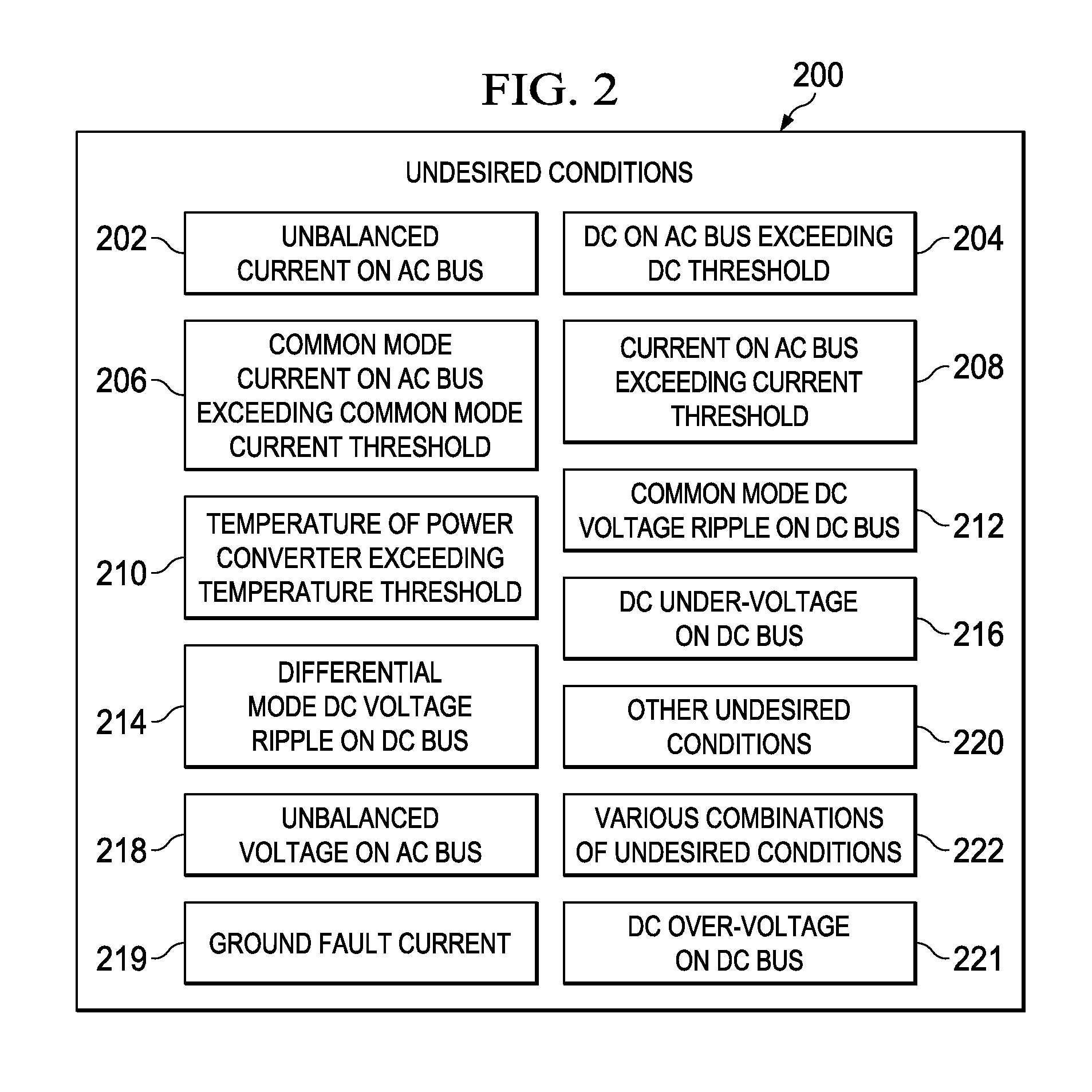
An apparatus and method for protecting a power system comprising a generator providing power to an alternating current bus, a power converter for converting alternating current power on the alternating current bus to direct current power on a direct current bus, and a direct current load powered by the direct current power on the direct current bus. An undesired condition is identified at the input to the power converter from the alternating current bus. The undesired condition is caused by at least one of the power converter, the direct current bus, or the load. The power converter is disconnected from the alternating current bus in response to identifying the undesired condition for at least a time delay. The time delay is selected such that the power converter is disconnected from the alternating current bus before the alternating current bus is disconnected from the generator due to the undesired condition.

Description

BACKGROUND INFORMATION[0001]1. Field[0002]The present disclosure relates generally to electrical power systems, such as systems for providing electrical power for motors and other loads on an aircraft. The present disclosure relates more specifically to alternating current power systems equipped with direct current power conversion equipment for providing electrical power to direct current loads and to identifying conditions in such power systems and protecting such systems from undesired conditions in a coordinated manner.[0003]2. Background[0004]Aircraft may employ various electronic devices and systems to perform various functions on the aircraft. For example, without limitation, electric motors on an aircraft may be used to move flight control surfaces, to pressurize hydraulics, to pump fuel, and to perform other functions on the aircraft. Power for the electric motors and other electronic systems and devices on an aircraft may be provided by an aircraft power system.[0005]Power...

Claims


Application Information

Patent Timeline
Patent Type & Authority Patents(United States)
IPC IPC(8): H02H7/09
CPCG05F1/66B60R16/03H02H7/125H02P1/021
Inventor SOLODOVNIK, EUGENE V.WHITE, JEFFREY J.
Owner THE BOEING CO
Learn More