Packet transmission device
a transmission device and packet technology, applied in data switching networks, instruments, frequency-division multiplexes, etc., can solve the problems of difficult inability to strictly keep the restriction, etc., and achieve the effect of ensuring the effect of maintaining the restriction
- Summary
- Abstract
- Description
- Claims
- Application Information
AI Technical Summary
Benefits of technology
Problems solved by technology
Method used
Image

Examples
first embodiment
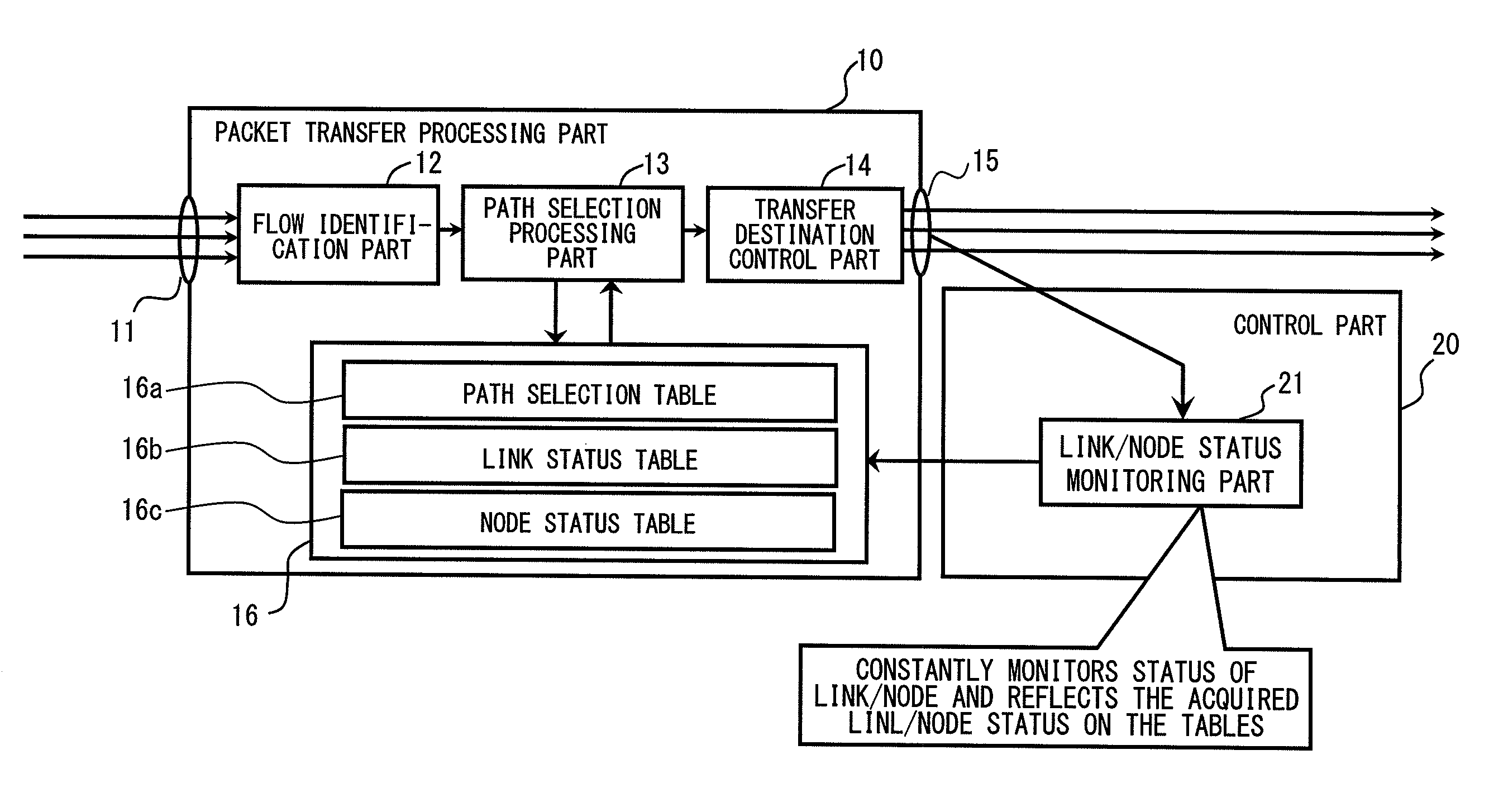
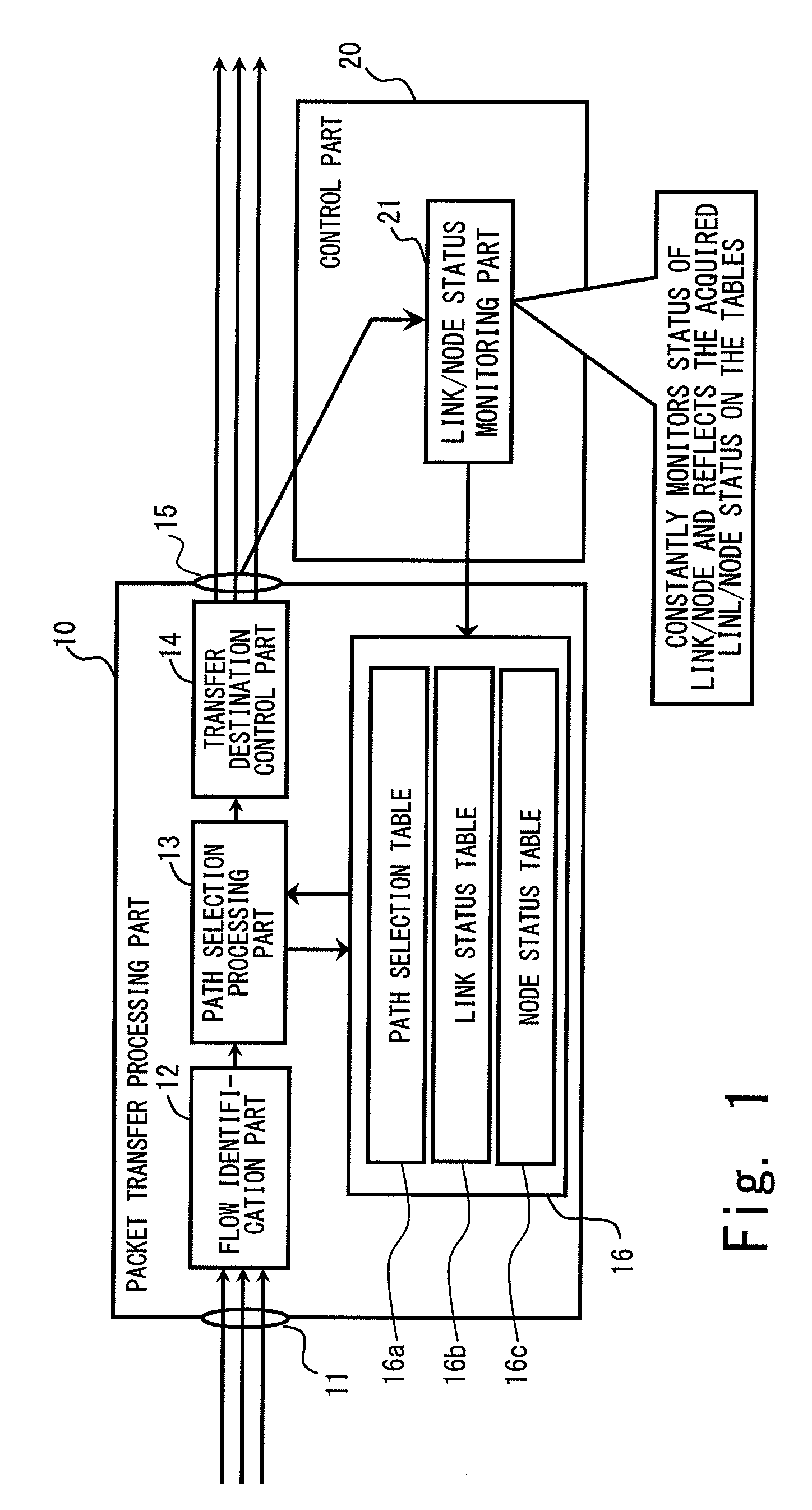
[0056]FIG. 1 is a block diagram illustrating a configuration of a packet transmission device (PE) according to a first embodiment of a packet transmission device according to the present invention. The packet transmission device according to the present invention is used as a router or a switch in a MPLS network, for example, shown in FIG. 16, the network in which several thousands of paths are established in one link.
[0057]As shown in FIG. 1, the PE according to the first embodiment includes a packet transfer processing part 10 and a control part 20 as a basic configuration.
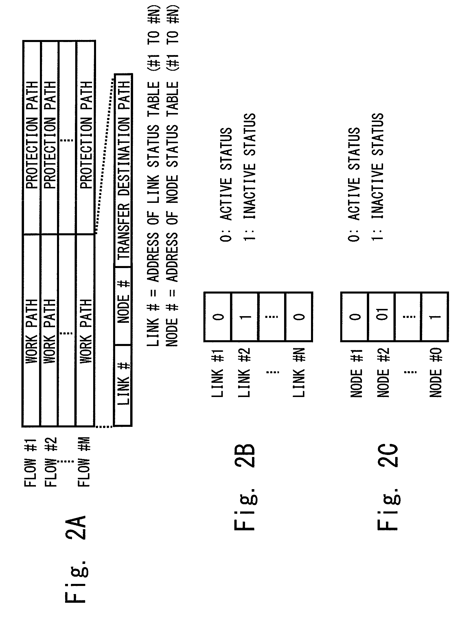
[0058]The packet transfer processing part 10 includes an input packet interface (input packet IF) 11, a flow identification part 12, a path selection processing part 13, a transfer destination control part 14, an output packet interface (output packet IF) 15, and a table memory 16. The table memory 16 stores a path selection table 16a, a link status table 16b, and a node status table 16c.
[0059]In the packet tra...
second embodiment
[0082]FIG. 6 is a block diagram illustrating a configuration of a packet transmission device (PE) according to the second embodiment of a packet transmission device according to the present invention. In the second embodiment, in addition to the local repair described in the first embodiment, an example of a configuration that can correspond to the global repair is shown. In FIG. 6, the same reference numbers are applied to structural elements the same or similar to those shown in FIG. 1 (first embodiment). In this description, parts concerning to the second embodiment will be mainly described.
[0083]As shown in FIG. 6, the packet transmission device (PE) according to the second embodiment has a packet transfer processing part 30 in place of the packet transfer processing part 10 of the configuration shown in FIG. 1 (first embodiment). In the packet transfer processing part 30, the path selection processing part 13 shown in FIG. 1 (first embodiment) is changed to a path selection pro...
third embodiment
[0096]FIG. 9 is a block diagram illustrating a configuration of a packet transmission device (PE) according to a third embodiment of a packet transmission device according to the present invention. In FIG. 9, the same reference numbers are applied to structural elements the same or similar to those shown in FIG. 1 (first embodiment). In this description, parts concerning to the third embodiment will be mainly described.
[0097]As shown in FIG. 9, the packet transmission device (PE) according to the third embodiment has a control part 40 in place of the control part 20 of the configuration shown in FIG. 1 (first embodiment). In the control part 40, a table display part 41 is added, and to the table display part 41, a personal computer 42 is connected.
[0098]FIG. 10 illustrates a display example of table contents that is displayed on a screen of the personal computer by the table display part shown in FIG. 9. The table display part 41 receives a command from the personal computer 42, rea...
PUM
 Abstract
Description
Claims
Application Information
 - R&D
- Intellectual Property
- Life Sciences
- Materials
- Tech Scout
- Unparalleled Data Quality
- Higher Quality Content
- 60% Fewer Hallucinations
Browse by: Latest US Patents, China's latest patents, Technical Efficacy Thesaurus, Application Domain, Technology Topic, Popular Technical Reports.
© 2025 PatSnap. All rights reserved.Legal|Privacy policy|Modern Slavery Act Transparency Statement|Sitemap|About US| Contact US: help@patsnap.com