
Discrete dynode detector with dynamic gain control

a dynamic gain control and detector technology, applied in the field of particle detector instruments, can solve the problems of reducing the secondary yield, inability to prevent strong electron currents from hitting the dynode near the output of the device, and insufficient beneficial design

Active Publication Date: 2014-05-27
THERMO FINNIGAN
View PDF17 Cites 23 Cited by
  • Summary
  • Abstract
  • Description
  • Claims
  • Application Information

AI Technical Summary

Benefits of technology

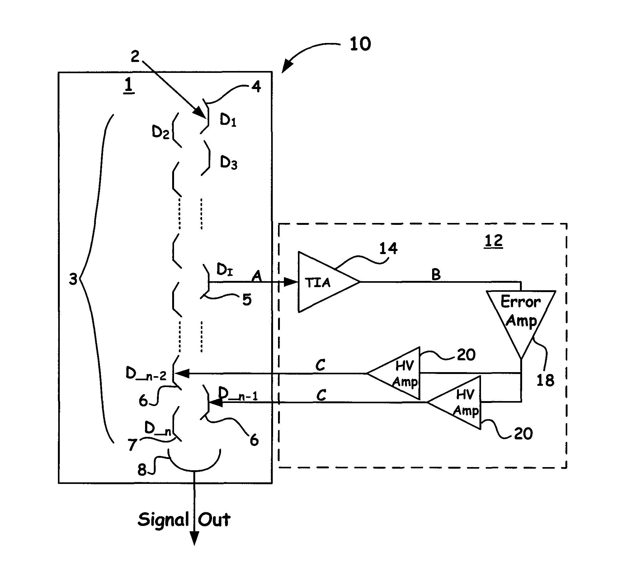
[0013]Accordingly, the present invention provides for an apparatus and method of operation that enables a user to prevent high current pulses (beyond the capacity of a dynode capacitor combination) to hit the dynodes. In particular, the methods, electron multiplier structures, and coupled control circuits of the present invention enable a resultant on the fly control signal to be generated upon receiving a predetermined threshold detection signal so as to enable the voltage regulation of one or more downstream dynodes near the output of the device.

Problems solved by technology

However, such high gain values and thus high secondary fluxes result in intense electron currents in the final stages of the current amplification along the various dynode structures.
While the use of discrete dynode architecture allows for better control of individual dynodes in the final part of the chain, the beneficial design still cannot in total prevent strong electron currents from hitting dynodes near the output of the device.
The accumulation of excessive carbon deposition has been attributed to the higher doses per unit area of secondary electrons from the dynodes near the anode that enable a carbon to become bonded to the dynode surfaces, which reduces the secondary yield.
As part of the phenomenon, the deleterious buildup of carbon occurs more rapidly in poor vacuum conditions, most typical of ion trap instruments.
However, while such approaches have been shown to somewhat ameliorate the aging process of the dynode structures, they are often not always desirable because of the technical challenges and associated costs.

Method used


Image

  • Discrete dynode detector with dynamic gain control
  • Discrete dynode detector with dynamic gain control
  • Discrete dynode detector with dynamic gain control

Examples


Embodiment Construction

[0017]In the description of the invention herein, it is understood that a word appearing in the singular encompasses its plural counterpart, and a word appearing in the plural encompasses its singular counterpart, unless implicitly or explicitly understood or stated otherwise. Furthermore, it is understood that for any given component or embodiment described herein, any of the possible candidates or alternatives listed for that component may generally be used individually or in combination with one another, unless implicitly or explicitly understood or stated otherwise. Moreover, it is to be appreciated that the figures, as shown herein, are not necessarily drawn to scale, wherein some of the elements may be drawn merely for clarity of the invention. Also, reference numerals may be repeated among the various figures to show corresponding or analogous elements. Additionally, it will be understood that any list of such candidates or alternatives is merely illustrative, not limiting, u...


PUM


Abstract

A novel electron multiplier that regulates in real time the gain of downstream dynodes as the instrument receives input signals is introduced. In particular, the methods, electron multiplier structures, and coupled control circuits of the present invention enable a resultant on the fly control signal to be generated upon receiving a predetermined threshold detection signal so as to enable the voltage regulation of one or more downstream dynodes near the output of the device. Accordingly, such a novel design, as presented herein, prevents the dynodes near the output of the instrument from being exposed to deleterious current pulses that can accelerate the aging process of the dynode structures that are essential to the device.

Description

BACKGROUND OF THE INVENTION[0001]1. Field of the Invention[0002]The present invention relates to the field of particle detector instrumentation. More particularly, the present invention relates to electron multipliers wherein real time signal generated by an intermediate dynode is monitored to regulate in real time the gain to dynodes near the output of the instrument.[0003]2. Discussion of the Related Art[0004]Electron multipliers are often utilized as detectors for the detection of particles such as photons, neutral molecules, and / or ions provided by mass spectrometry. While the geometry of such devices can vary, a common beneficial design comprises a cathode, an anode, and a chain of resistors and capacitors coupled to a plurality of about 10-25 discrete electron multiplier disposed structures (dynodes). Collectively, such an arrangement provides a plurality of stages that when operated with voltages between about 1000-5000V enable gains often between about than 105 up to about 1...

Claims


Application Information

Patent Timeline
Patent Type & Authority Patents(United States)
IPC IPC(8): H01J43/04H01J43/18H01J43/24
CPCG01T1/16H01J43/04H01J43/24H01J43/18H01J43/30H01J40/14H01J49/025
Inventor KOVTOUN, VIATCHESLAV V.MATHUR, RAMAN
Owner THERMO FINNIGAN
Learn More