Treatment of spent caustic waste
a technology of caustic waste and treatment conditions, applied in the nature of treatment water, multi-stage water/sewage treatment, other chemical processes, etc., can solve the problem that the operation conditions suitable for the treatment of some process streams may not be suitable for the treatment of different process streams
- Summary
- Abstract
- Description
- Claims
- Application Information
AI Technical Summary
Benefits of technology
Problems solved by technology
Method used
Image

Examples
example 1
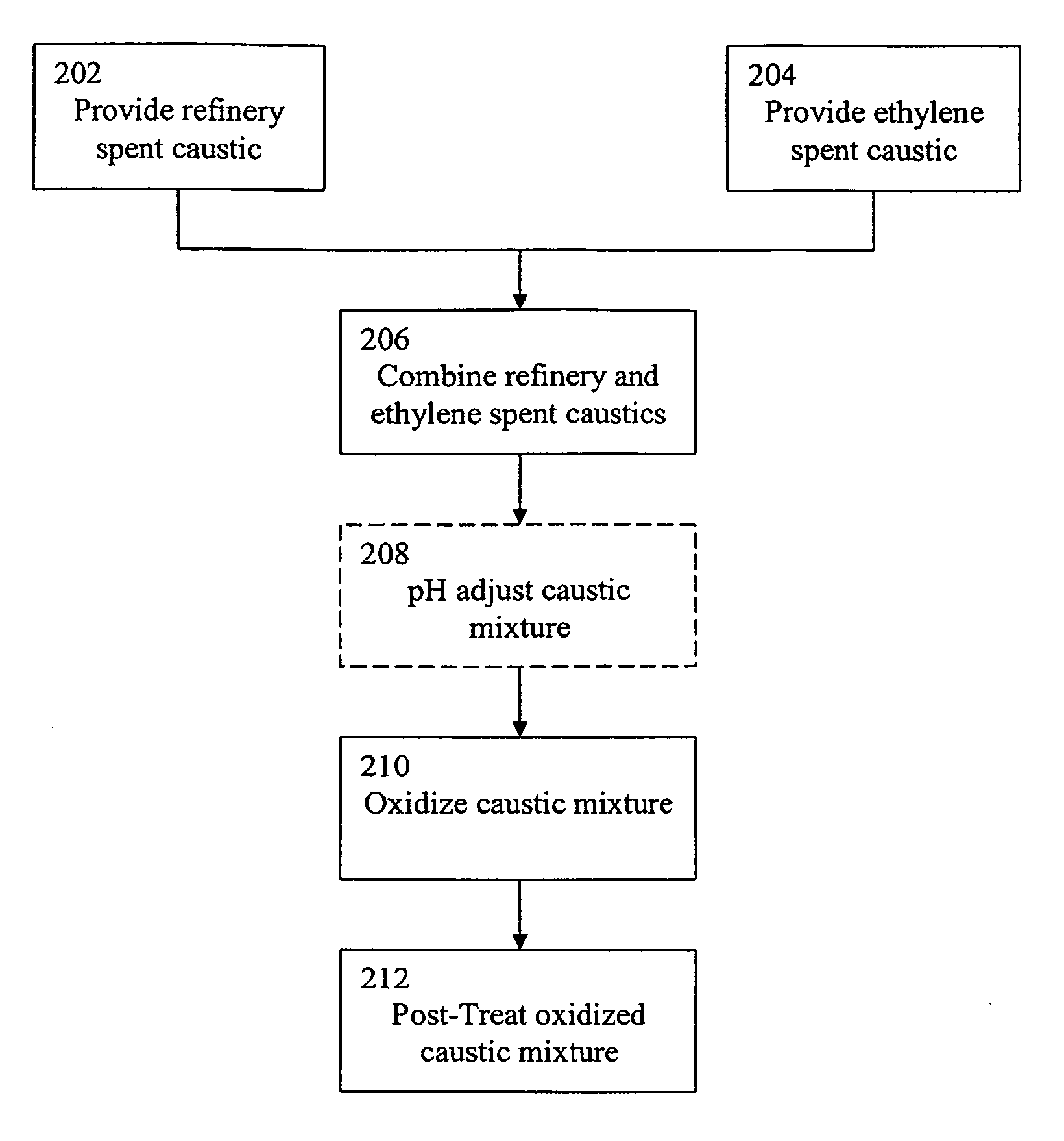
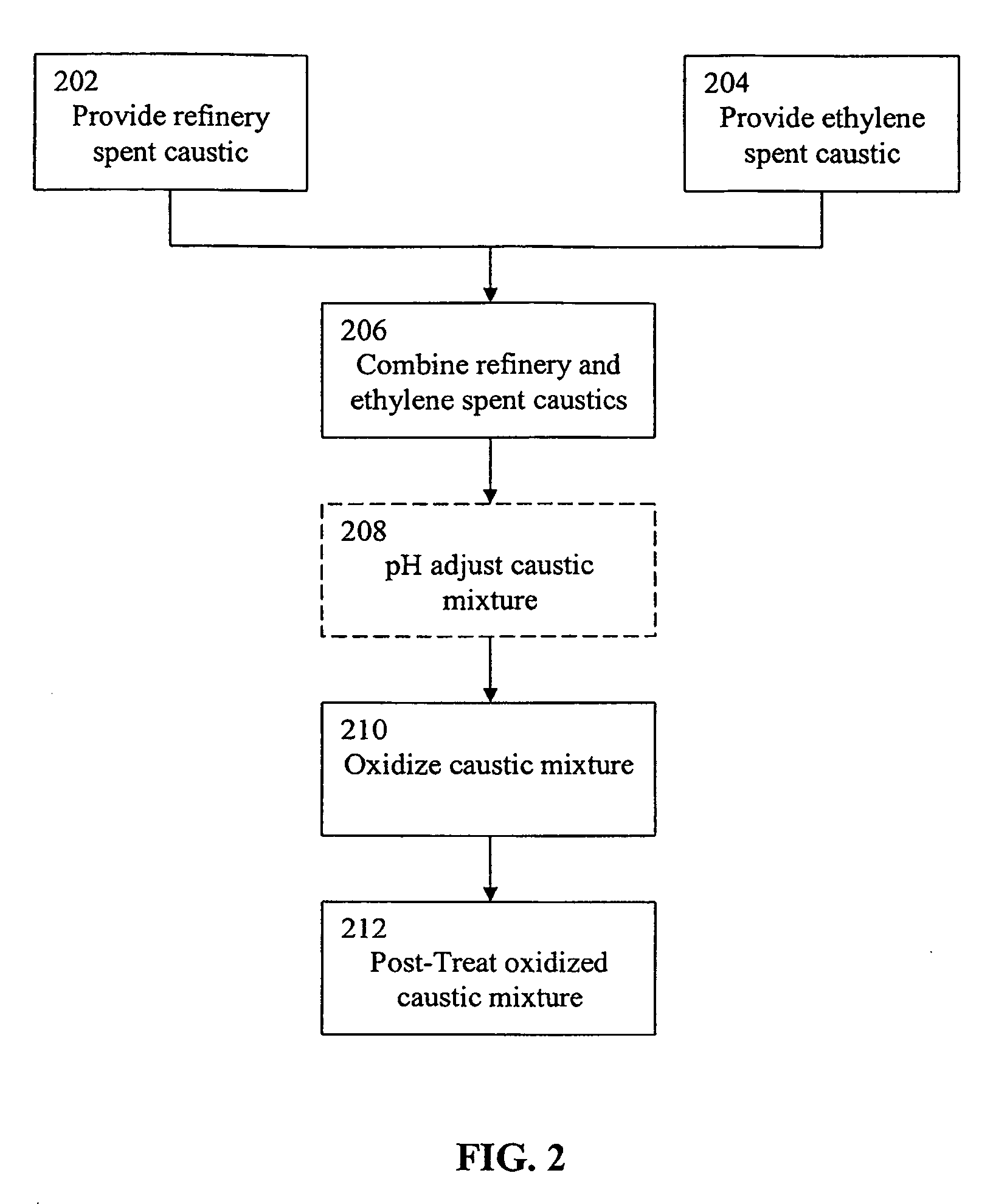
Comparison of the WAO Treatment of Refinery Spent Caustic Diluted with Water Versus Refinery Spent Caustic Diluted with Ethylene Spent Caustic
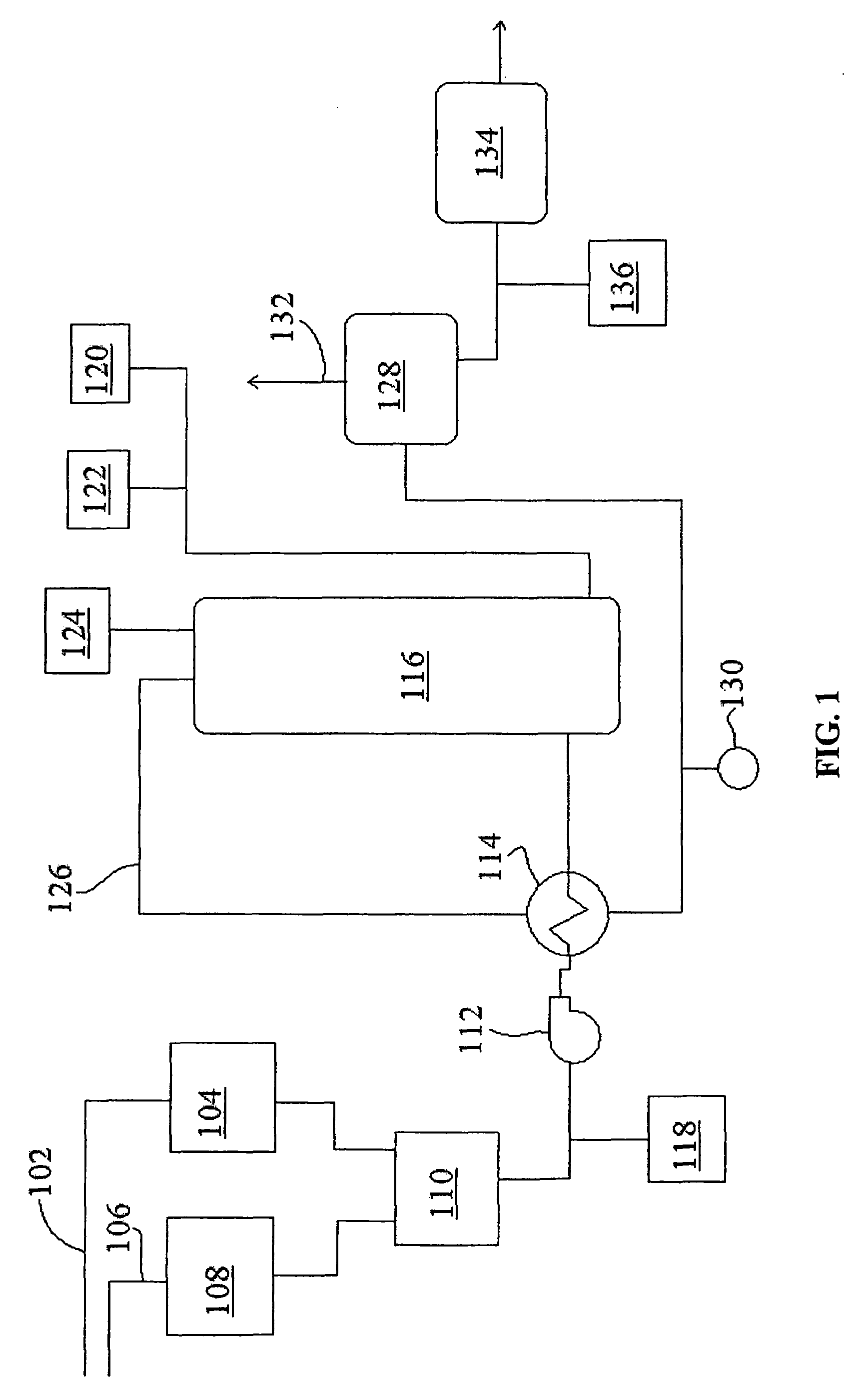
[0089]A mixture of approximately 74% ethylene spent caustic and 16% refinery spent caustic was treated in a WAO unit as shown in FIG. 1 at 240° C. with a hydraulic retention time of 90 minutes. The COD destruction level and the pH of the effluent of the reaction vessel were measured. These quantities were compared to those achieved by treating a naphthenic spent caustic under the same conditions. As can be seen in Table 4 below, the COD destruction of the mixed caustics was approximately 84% while the COD destruction of the naphthenic spent caustic diluted with water was approximately 79%. Also, the data shows that the ethylene spent caustic buffered the pH of the refinery spent caustic during the oxidation process; the oxidized refinery spent caustic diluted with water displayed a pH of 8.2 while the oxidized refinery spent caustic diluted wi...
example 2
Reduction in Caustic pH vs. COD Removal
[0091]Samples of a spent caustic were obtained from a diesel wash process from a refinery and treated in a wet air oxidation unit as shown in FIG. 1. The samples were diluted with water in order to reduce the COD of the samples and divided into two groups. Control tests of diluted spent caustic samples all having a pH of greater than 12 were oxidized in a WAO at a temperature of 260° C. and a pressure of about 80 atm for about 1 hour. The COD destruction for each ranged from about 60% to about 70%.
[0092]The pH of the other group of samples was reduced to about 10.5 by the addition of sulfuric acid. These samples were oxidized in a WAO at a temperature of 240° C. and pressures ranging from about 60 atm for about 1 hour. The COD destruction for each pH adjusted sample was about 80%. The addition of the acid to reduce the pH of the spent caustic generally improved efficiency by as much as about 10%, even when oxidized at a lower temperature and pr...
example 3
pH Reduction of Caustic with Sulfuric Acid vs. with Carbon Dioxide
[0093]Two samples of refinery spent caustic were treated in a WAO system, each at 240° C. with a hydraulic residence time of 90 minutes. Prior to treatment, one of the samples was pH adjusted by the addition of sulfuric acid, while the other was pH adjusted by the addition of carbon dioxide. The data presented below in Table 5 was obtained from continuous flow pilot data. It can be seen from this data that performing WAO after pH reduction with carbon dioxide resulted in a higher COD reduction (approximately 80%) relative to the same process performed with a pH reduction performed by the addition of sulfuric acid to the spent caustic (a COD reduction of approximately 72%). Without being bound by any particular theory, it is believed that some of the organics in the spent caustic are converted into acid oils when the pH is lowered using a strong acid such as sulfuric acid. When carbon dioxide is used, these organics re...
PUM
| Property | Measurement | Unit |
|---|---|---|
| temperature | aaaaa | aaaaa |
| temperature | aaaaa | aaaaa |
| COD | aaaaa | aaaaa |
Abstract
Description
Claims
Application Information
 - R&D
- Intellectual Property
- Life Sciences
- Materials
- Tech Scout
- Unparalleled Data Quality
- Higher Quality Content
- 60% Fewer Hallucinations
Browse by: Latest US Patents, China's latest patents, Technical Efficacy Thesaurus, Application Domain, Technology Topic, Popular Technical Reports.
© 2025 PatSnap. All rights reserved.Legal|Privacy policy|Modern Slavery Act Transparency Statement|Sitemap|About US| Contact US: help@patsnap.com