Electric breast milk pump

a breast milk pump and electric technology, applied in the direction of milking pumps, suction devices, intravenous devices, etc., can solve the problems of limited flow in pressure compensation and milk gradually jamming above the outlet valve, and achieve the effect of compact construction and short tim

Active Publication Date: 2014-05-27
MAPA
View PDF3 Cites 1 Cited by
  • Summary
  • Abstract
  • Description
  • Claims
  • Application Information

AI Technical Summary

Benefits of technology

[0026]The present invention is based on the finding that in the known breast milk pump with electronically controlled venting valve, the pressure compensation in the suction cup does not occur quickly enough in the venting phases at short cycles or high milk flows, respectively, so that the milk pumped off does not or not sufficiently flow away into the reservoir via the outlet valve. As a consequence, it can occur that the milk gradually jams above the outlet valve, rises up to the seal seat of the floater valve and arrives in the interior of the pump. This can happen with small breast milk pumps in particular, in which the venting line and the venting valve have small dimensions, whereby the flow in the pressure compensation is limited. According to the present invention, this problem is overcome in that in the operating mode, air is actively pumped into the connection channel, and thus into the suction cup and the outlet in the pressure phases, so that the pressure above the outlet valve can be brought to the surroundings pressure, or even to a small overpressure with respect to the surroundings pressure, more quickly than with passive venting. The outlet valve opens through the increased pressure above the outlet valve. As a consequence, the milk pumped off in the suction phases and standing above the outlet valve can flow down with sufficient speed into the reservoir through the outlet valve between the suction phases, and does not rise up to the valve seat of the floater valve. The milk flows off particularly quickly when a small overpressure against the surroundings pressure is set in the connection channel. The period of time for actively pumping air into the connection channel can be shorter than the span between two consecutive suction phases. In the remaining time between two suction phases, the electric motor can be switched off in order to save energy and to reduce the motor's wear. In the idle mode, the electric motor is also switched off.
[0029]According to one embodiment, there are means for adjusting the speed of the electric motor, and the electronic control system is configured such that it operates the electric motor with a speed according to the setting of the means for adjusting the speed. Through this, the suction underpressure generated by the pump can be adjusted according to requirements. Compared to breast milk pumps in which the suction underpressure can be adjusted by means of a permanent, adjustable venting, less electric energy is required and the wear of the electric motor is reduced. According to a further embodiment, the electronic control system is configured such that it operates the electric motor continuously or in cycles according to the setting of the means for adjusting. Depending on the requirements of the user, the pump can work continuously or in cycles with suction- and pressure phases, and as the case may be, with venting phases.
[0036]According to a further embodiment, the pump is a membrane pump. By means of a membrane pump, the necessary suction underpressures can be built up in a short time with compact construction. The suction underpressures are preferably in the range of 330 to 50 mbar. In the suction phases, these suction underpressures can be built up by means of a membrane pump within a time in the range of seconds, or even below. Instead of a membrane pump, a reciprocating pump or a hose pump can be used in particular.

Problems solved by technology

As a consequence, it can occur that the milk gradually jams above the outlet valve, rises up to the seal seat of the floater valve and arrives in the interior of the pump.
This can happen with small breast milk pumps in particular, in which the venting line and the venting valve have small dimensions, whereby the flow in the pressure compensation is limited.

Method used


Image

  • Electric breast milk pump
  • Electric breast milk pump
  • Electric breast milk pump

Examples


Embodiment Construction

[0049]While this invention may be embodied in many different forms, there are described in detail herein a specific preferred embodiment of the invention. This description is an exemplification of the principles of the invention and is not intended to limit the invention to the particular embodiment illustrated.

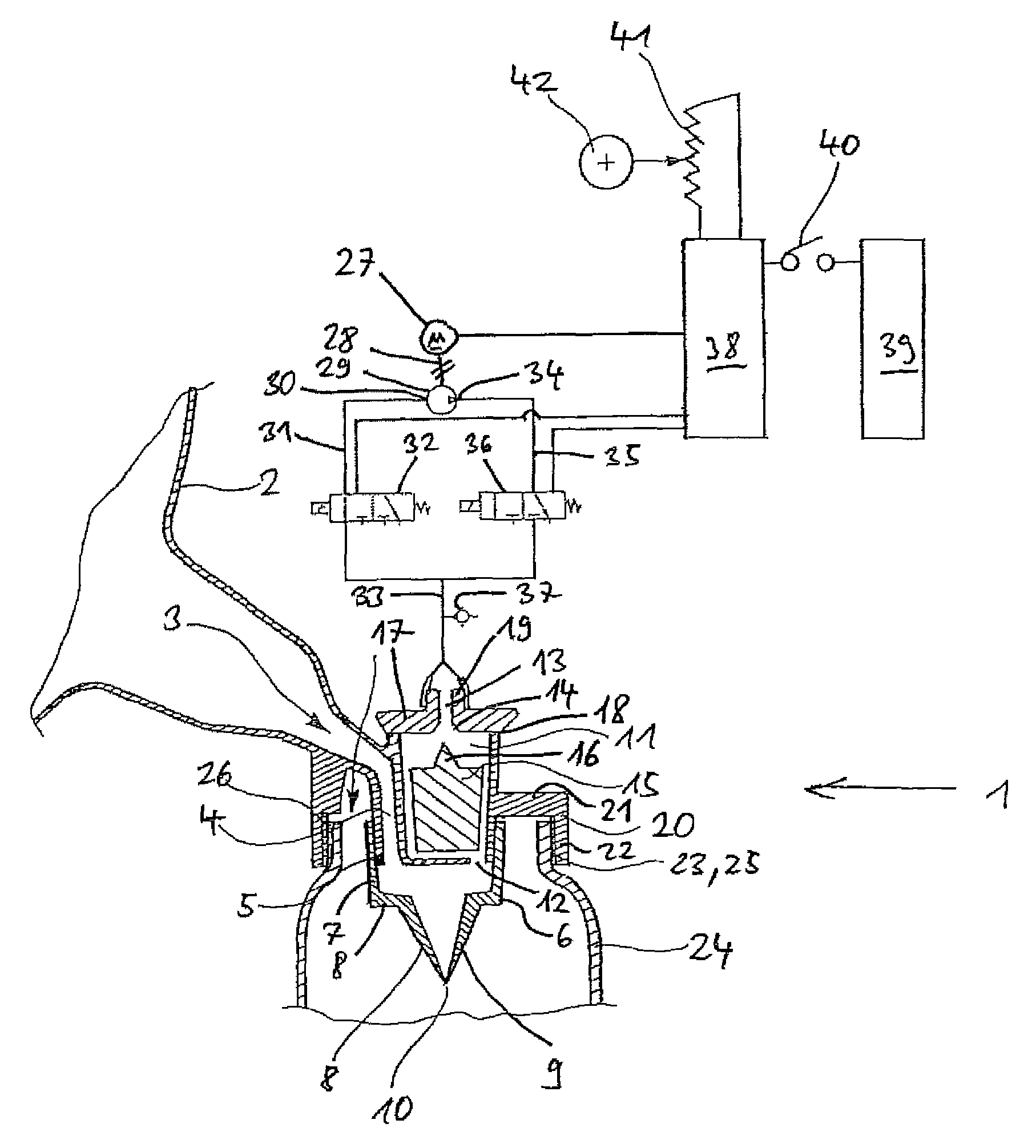
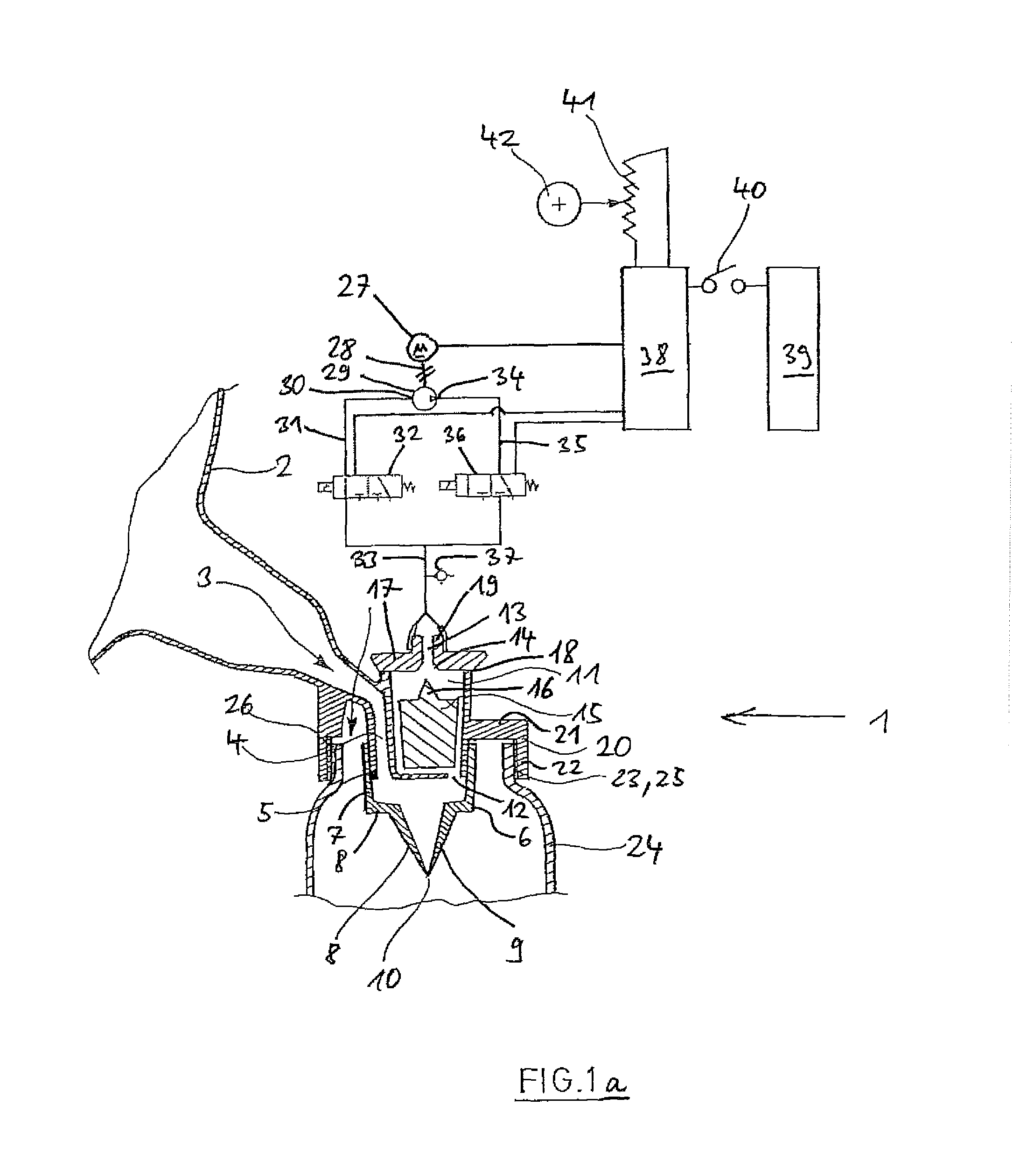
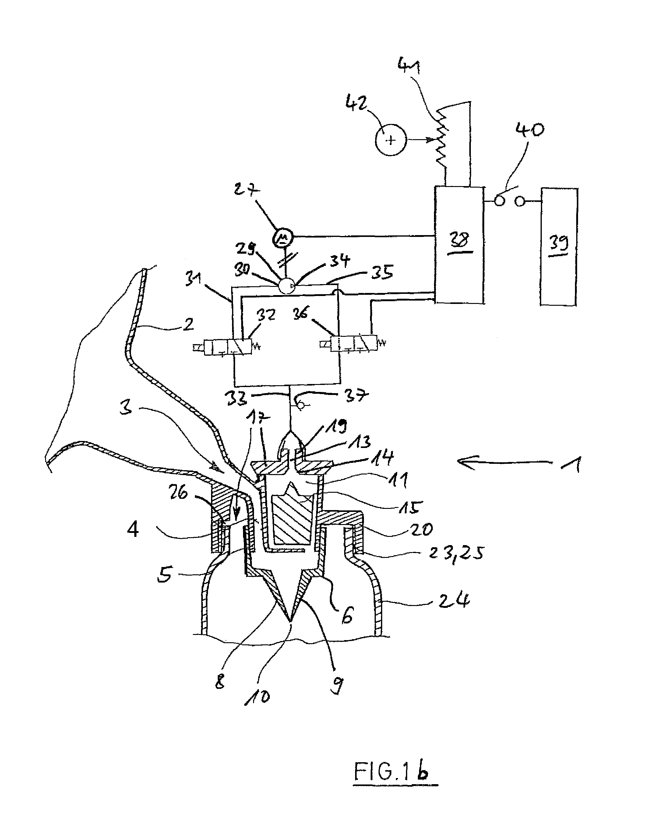
[0050]According to FIGS. 1a and 1b, a breast milk pump 1 has a suction cup 2, which broadens towards the outside and has an opening 3 to a connection channel 4 at its inner end. At the lower end, the connection channel 4 merges into an outlet 5 in the form of a vertically directed pipe neck.

[0051]On the outlet 5 sits a discharge valve 6 in the form of a duckbill valve. The duckbill valve 6 is made of an elastic and inert material, for instance of silicone rubber or latex. At its upside, the duckbill valve 6 has a pipe-shaped portion 7, which has a valve bottom 8a at the downside, from which two flat legs 8, 9 project towards the downside. The duckbill valve 6 is clamped onto ...


PUM


Abstract

A breast milk pump having an electric motor, a pump driven by the motor, a suction cup, an electrically activated first three-way valve in a suction line, an electrically activated second three-way valve in a pressure line, an electronic control system, which sets the electric motor into an operating mode or an idle mode depending on an activation of a switch; in the operating mode, it operates the electric motor and the electrically activated first and second three-way valves in cycles, which comprise a suction phase, in which the electric motor is switched on, the inlet of the pump is connected to the suction cup via the first three-way valve and a floater valve, the pump outlet is connected via the second three-way valve.

Description

CROSS-REFERENCE TO RELATED APPLICATIONS[0001]Not applicable.STATEMENT REGARDING FEDERALLY SPONSORED RESEARCH[0002]Not applicable.BACKGROUND OF THE INVENTION[0003]The present invention relates to an electric breast milk pump.[0004]Breast milk pumps serve for pumping away breast milk. For this purpose, they have at least one suction cup, which is set onto the mother's breast. An underpressure is applied to the suction cup in order to withdraw the milk from the mother's breast. This underpressure will also be designated as “suction underpressure” in the following. The suction cup is connected to a reservoir, which receives the breast milk that is suck off. The underpressure is generated by means of a pump, which is driven manually or by means of an electric motor. Electric breast milk pumps driven by means of an electric motor are known, which have an electronic control system which controls certain pumping sequences. In these pumping sequences, the pump is switched on and off during d...

Claims


Application Information

Patent Timeline
Patent Type & Authority Patents(United States)
IPC IPC(8): A61M1/06
CPCA61M1/005A61M1/0037A61M1/0049A61M1/06A61M1/75A61M1/78A61M1/782A61M1/742
Inventor JAGER-WALDAU, REINHOLD
Owner MAPA
Why Eureka
Try Eureka